


The unmanned aerial vehicle (UAV) sector is dominated by proprietary, closed-loop radio systems that lock users into specific ecosystems. If you are an engineering student, an open-source advocate, or an ambitious hobbyist, relying blindly on off-the-shelf commercial radios deprives you of understanding the fundamental physics of flight control. Learning how to make a DIY drone transmitter and receiver at home is the ultimate rite of passage in radio frequency engineering and micro-controller programming.
From our experience engineering advanced telemetry and data links at China Moneypro, we hold a firm, uncompromising stance on custom radio builds: they are brilliant educational tools but absolute liabilities in commercial airspace. You must understand whether your specific application warrants a homemade radio. If you are flying a 250-gram foam glider in an empty park, a $20 Arduino-based radio is an incredible achievement. However, if you are commanding a payload-bearing UAV over populated areas, relying on a breadboard and jumper wires is commercial suicide.
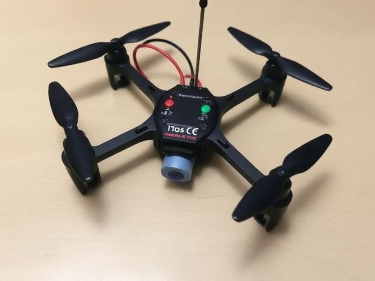
In this comprehensive guide, we will strip away the mystery of radio control. We will walk you through the exact architecture of a homemade RF system, explain the limitations of the hardware, and provide the hard truths about when you must abandon DIY projects in favor of professional-grade data links.
Quick Answer: The Build Process & Verdict
To successfully make a DIY drone transmitter and receiver at home, you must follow these 6 sequential steps:
- Source the Hardware: Acquire two microcontrollers (e.g., Arduino Nano), two RF modules (NRF24L01+ with PA/LNA), and analog joysticks.
- Wire the Transmitter (Tx): Connect the joysticks and one RF module to the first microcontroller.
- Wire the Receiver (Rx): Connect the second RF module to the receiving microcontroller.
- Program the Microcontrollers: Write and flash the C++ code to read analog inputs, format data packets, and handle RF transmission via the SPI bus.
- Bind and Test: Monitor the serial output to ensure data packets are transmitting and being received with minimal latency.
- Integrate with the Flight Controller: Output the received data as a PWM or PPM signal to your drone’s flight controller.
The Verdict: Building your own Tx/Rx is highly recommended for beginners learning the fundamentals of drone logic and mechatronics. It is strictly prohibited for commercial users operating heavy machinery, where guaranteed signal integrity and encryption are non-negotiable.
Table of Contents
- What is a Drone Transmitter and Receiver?
- How a DIY RF System Works
- The 6 Steps to Build Your System
- Benefits of Building Your Own Radio
- Limitations and Hard Truths
- Who Should Use It & Who Shouldn’t
- Common Mistakes in DIY Radios
- Expert Buying Considerations
- Summary and Comparison Tables
- Expert Recommendation: Upgrading to Commercial Links
- Frequently Asked Questions (FAQ)
What is a Drone Transmitter and Receiver?
A drone transmitter (Tx) is the handheld ground station that translates your physical joystick movements into digital data. The receiver (Rx) is the onboard module physically connected to the drone’s flight controller. The flight controller takes the instructions from the receiver and translates them into motor speeds and servo actuations.
When you make a DIY drone transmitter and receiver at home, you are essentially building a custom data bridge. Instead of relying on protocols like FrSky, ExpressLRS, or Futaba FASST, you define your own data payload structure, dictating exactly how many channels of control you have and what specific frequency hopping algorithms you deploy.
How a DIY RF System Works
The architecture relies on the Serial Peripheral Interface (SPI) protocol to communicate between the microcontroller and the radio transceiver chip. In a typical Arduino-based build, the analog joysticks send variable voltage signals (0-5V) to the Arduino’s analog pins. The Arduino converts these voltages into a 10-bit digital value (0-1023), maps them to a byte array, and sends that array to an RF module like the NRF24L01+.
The NRF24L01+ blasts that data packet through the air on the 2.4GHz ISM band. The receiving NRF24L01+ catches the packet, verifies the checksum, and hands the data to the receiving Arduino. This receiving Arduino then translates the digital array back into Pulse Width Modulation (PWM) signals, which traditional flight controllers require to adjust throttle, pitch, roll, and yaw.
The 6 Steps to Build Your System
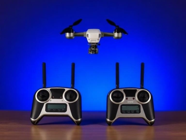
Step 1: Source the Correct Hardware
Avoid buying cheap knockoff components, as their voltage regulators frequently fail. You will need:
- 2x Microcontrollers (Arduino Nano or ESP32 for faster processing).
- 2x RF Modules (NRF24L01+ with PA/LNA antennas for extended range, or LoRa SX1278 modules for lower frequency, higher penetration).
- 2x Analog 2-axis joysticks.
- Toggle switches (for arming and flight modes).
- Jumper wires, perfboard, and soldering equipment.
Step 2: Wire the Transmitter (Tx)
You must establish a rock-solid electrical connection. Connect the joystick potentiometers to the analog pins (A0 through A3) of the primary Arduino. Connect the NRF24L01+ module to the Arduino using the standard SPI pins (MOSI, MISO, SCK, CE, CSN). Crucial Note: The NRF24L01+ requires strict 3.3V power. Do not connect it to the 5V rail of the Arduino, or you will instantly fry the transceiver.
Step 3: Wire the Receiver (Rx)
On the drone side, wire the second NRF24L01+ to the second Arduino using the same SPI pin configuration. You must also designate digital output pins (e.g., D3, D5, D6, D9) that support PWM generation, as these will eventually connect to your flight controller.
Step 4: Program the Microcontrollers
In the Arduino IDE, utilize the RF24.h library. Your Transmitter code must define a data structure (a struct) containing variables for throttle, yaw, pitch, and roll. The code will read the analog pins, map the values from 0-1023 to standard RC values (1000-2000 microseconds), and utilize radio.write() to transmit the packet. The Receiver code will continuously listen using radio.available() and write the received values to the PWM output pins using the Servo.h library.
Step 5: Bind and Test the Serial Output
Before installing the receiver on a drone, power both units via USB. Open the Serial Monitor in the Arduino IDE. Move the joysticks on the Tx and watch the values update on the Rx Serial Monitor in real-time. If you experience massive data drops or lag, you likely need to solder a 10µF to 100µF electrolytic capacitor across the 3.3V and GND pins of the NRF24L01+ modules to stabilize the power supply.
Step 6: Integrate with the Flight Controller
Once stable, connect the PWM output pins of the Rx Arduino to the input channels of your drone’s flight controller (such as Pixhawk or Betaflight). Verify the channel mapping (AETR – Aileron, Elevator, Throttle, Rudder) matches the software configuration in your ground control station software.
Benefits of Building Your Own Radio
The primary benefit of a DIY radio is profound education. When you write the code handling packet loss, you understand why commercial drones feature complex fail-safe mechanisms. Furthermore, custom builds allow for infinite I/O expansion. If you are building experimental fixed wing drones and need 16 custom switches to drop sensors, trigger servos, and deploy parachutes, programming an Arduino is vastly cheaper and more flexible than buying a $1,500 24-channel commercial radio.
Limitations and Hard Truths
We must present practical judgment: an Arduino paired with a basic 2.4GHz module is inherently vulnerable. The processing overhead of generating clean PWM signals on an 8-bit microcontroller introduces latency. While a commercial ExpressLRS link boasts 150Hz to 500Hz refresh rates, a poorly coded Arduino link might struggle to hit 50Hz, making acrobatic flight impossible.
Furthermore, standard NRF24L01+ modules lack Frequency-Hopping Spread Spectrum (FHSS) capabilities out of the box. If you fly your DIY drone in an urban area saturated with Wi-Fi routers, the interference will drown out your signal, leading to an immediate flyaway or crash. This is why for serious operations, such as piloting a bvlos fixed wing uav, DIY links are legally and practically unacceptable.
Who Should Use It & Who Does Not Need It
Who Should Use It: We recommend DIY radios exclusively for beginners, STEM educators, robotics students, and hobbyists building low-speed ground rovers or small, lightweight park-flyer drones where a crash carries zero financial or physical risk.
Who Does Not Need It: For commercial users, surveyors, and enterprise operators, a DIY radio is an active hazard. If you are operating a heavy lift vtol drone carrying thousands of dollars in LiDAR equipment, you require professional telemetry links featuring AES-256 encryption, dual-band redundancy, and guaranteed MIMO (Multiple-Input Multiple-Output) reliability.
Common Mistakes in DIY Radios
If your transmitter loses power, what does the receiving Arduino do? If you did not program the Rx to detect a timeout and automatically drop the throttle PWM signal to 1000us, the drone will simply lock onto the last received command and fly away at full speed until the battery dies. Always code a timeout fail-safe.
Expert Buying Considerations: When to Upgrade
You must recognize when you have outgrown DIY. Once your airframe exceeds 2 kilograms, or your flight envelope extends beyond visual line of sight (BVLOS), you must transition to commercial hardware. When flying a long range drone with camera capabilities, you need a combined data link that handles not just RC control, but high-definition video feeds and bidirectional MavLink telemetry simultaneously. An Arduino cannot process HD video; it requires dedicated digital mesh network radios.
Summary and Comparison Tables
Quick Summary Table: The 6 DIY Steps
| Step | Action | Critical Component / Skill |
|---|---|---|
| 1. Sourcing | Acquire microcontrollers and RF modules. | Arduino Nano, NRF24L01+ (PA/LNA) |
| 2. Tx Wiring | Connect joysticks and RF module to Arduino. | 3.3V power regulation, SPI pins |
| 3. Rx Wiring | Connect RF module to receiving Arduino. | SPI pins, PWM output pin mapping |
| 4. Programming | Write code for data packaging and transmission. | C++, RF24.h library, Structs |
| 5. Testing | Verify data flow via Serial Monitor. | Latency checking, Capacitor filtering |
| 6. Integration | Output PWM signals to Flight Controller. | Servo.h library, AETR mapping |
Comparison Table: DIY vs. Commercial Radio Links
| Feature | DIY Arduino Radio (NRF24L01+) | Commercial Digital Datalink |
|---|---|---|
| Cost | Under $30 | $500 to $5,000+ |
| Effective Range | 100m to 1km (highly variable) | 30km to 150km+ |
| Encryption | None (Easily spoofed/hacked) | AES-128 / AES-256 |
| Frequency Hopping | Manual programming required (complex) | Automated FHSS / MIMO technology |
| Best Use Case | Educational, park flyers, rovers | Enterprise VTOL, Cargo, BVLOS |
Pros and Cons of DIY Drone Radios
| Pros (Advantages) | Cons (Limitations) |
|---|---|
| Extremely low cost barrier to entry. | High susceptibility to RF interference. |
| Provides deep understanding of SPI, PWM, and C++. | Lacks native fail-safe mechanisms without custom coding. |
| Infinite customization for non-standard switches/sensors. | Hardware unreliability (cheap voltage regulators fail). |
| Open-source libraries make integration straightforward. | Strictly prohibited for commercial/enterprise flight operations. |
Expert Recommendation: Upgrading to Commercial Links
If you are transitioning from a hobbyist experimenting in your garage to a commercial operator piloting a vtol cargo drone, the radio link is your most critical lifeline. Do not compromise your payload or public safety by relying on unencrypted, low-power transmitters.
In most professional situations, we recommend integrating industrial-grade mesh networking systems. These systems combine your RC control, MavLink telemetry, and HD video feed into a single, highly encrypted digital stream that automatically routes around RF interference.
China Moneypro Unmanned Drone Data Link
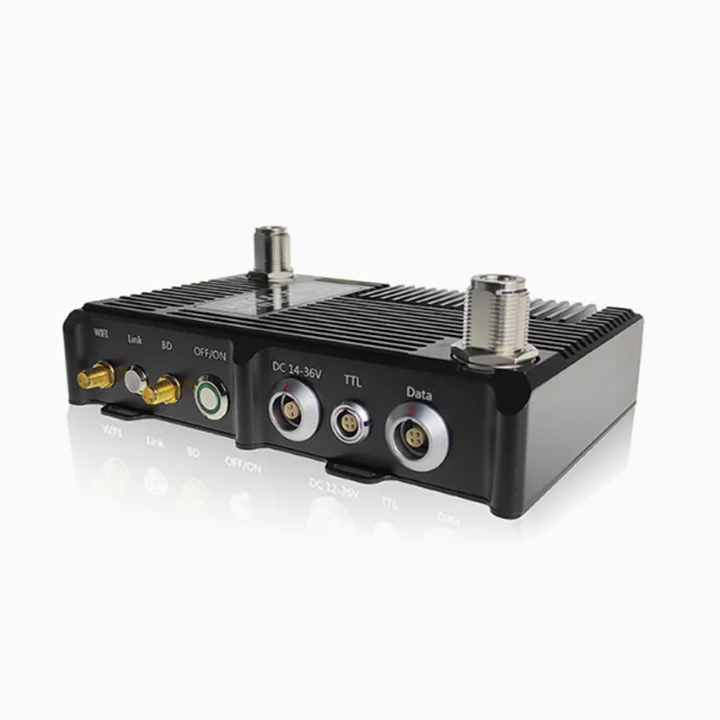
For heavy-duty applications, the China Moneypro Unmanned Drone Data Link MIMO Mesh Network Radio represents the pinnacle of digital transmission. Designed specifically for complex UAV deployments, it offers robust, long-range connectivity that DIY solutions cannot physically replicate.
- Information Content: Text, Picture, Video, Audio integration.
- Frequency Range: 1428~1448MHz (Standard) / 1100~1500MHz (Customized for global compliance).
- Networking Capabilities: Supports ≥ 52 Nodes in a self-healing MIMO mesh.
- Security: Military-grade AES128/256 Encryption.
- Power Output: 8W (4W * 2) for extreme BVLOS penetration.
long range vtol drone, ensuring that your command and control infrastructure matches the sophisticated engineering of your airframe.
Frequently Asked Questions (FAQ)
Is it legal to build and use my own drone transmitter?
In most countries, including the United States, utilizing the 2.4GHz ISM (Industrial, Scientific, and Medical) band for low-power hobbyist transmission is perfectly legal without a specialized license. However, if you modify the transmitter with high-gain amplifiers to exceed specific wattage limits, you violate federal communication laws and may require a HAM radio license.
Why do DIY drone receivers lose signal so easily?
DIY modules like the NRF24L01+ often suffer from signal loss due to poor power filtering. The 3.3V regulators on Arduino boards cannot handle the sudden current spikes required during transmission. Adding a bypass capacitor across the power pins of the RF module usually stabilizes the signal.
Can an Arduino read an SBUS receiver directly?
SBUS is an inverted serial protocol. To read SBUS data on a standard Arduino, you must either build a physical hardware inverter circuit using an NPN transistor and resistors, or use software-based inversion libraries if using microcontrollers with flexible UARTs, such as the ESP32 or Teensy.
Authoritative References & Industry Standards
For further technical reading on radio frequency engineering, compliance, and UAV communication protocols, we recommend reviewing the following authoritative sources:
- Federal Communications Commission (FCC): Guidelines and regulations regarding the legal power limits and use of the 2.4GHz ISM band. Visit the FCC Equipment Authorization Guide
- Institute of Electrical and Electronics Engineers (IEEE): Technical standards for wireless networking and radio frequency modulation techniques. Visit IEEE Standards
- Federal Aviation Administration (FAA): Safety regulations and operational limits concerning unmanned aircraft systems (UAS) and command/control link requirements. Visit the FAA UAS Guidelines