


In modern commercial UAV operations, relying solely on satellite positioning is an act of professional negligence. When a high-value enterprise drone is navigating through complex urban corridors, inspecting dense forestry, or operating in contested airspace, signal multipath and active radio frequency jamming are not hypotheticals—they are guaranteed operational hazards. If a standalone Global Navigation Satellite System (GNSS) receiver loses its positional fix, the flight controller is instantly blinded. The result is typically a catastrophic flyaway or structural loss of the airframe. To survive and execute in these high-stakes environments, commercial operators must deploy industrial-grade GNSS/INS Integrated Navigation Systems.
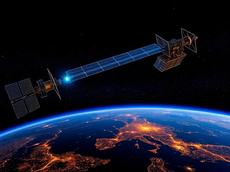
From our experience engineering elite enterprise drone solutions at China Moneypro, true autonomous flight requires the relentless, seamless mathematical fusion of external satellite data and internal inertial physics. Treating navigation as a simple “GPS plug-and-play” module is a fundamental misunderstanding of aviation avionics. In this comprehensive technical guide, we will brutally dissect the working principles behind sensor fusion, explore the critical commercial applications that demand this technology, and provide strict, uncompromising buying criteria for selecting the exact navigation architecture that guarantees mission success.
Quick Answer: The Ultimate Navigation Synergy
What are GNSS/INS Integrated Navigation Systems? They are advanced avionics architectures that mathematically fuse absolute spatial positioning data from satellite constellations (GNSS) with high-frequency motion and orientation data from an onboard Inertial Navigation System (INS). The GNSS provides the absolute geographical truth to continuously correct the inherent long-term drift of the inertial sensors. Conversely, the INS bridges the navigation gaps during satellite signal outages and provides noise-free, high-rate attitude data (roll, pitch, yaw). This continuous complementary feedback loop yields seamless, tactical-grade positioning, velocity, and orientation updates at rates up to 400Hz.
Table of Contents
- What is a GNSS/INS Integrated Navigation System?
- The Working Principles: How Sensor Fusion Solves Drift
- Critical Industrial Applications for UAVs
- The Benefits of Upgrading to GNSS/INS
- Technical Limitations and Operational Constraints
- Who Should Use It & Who Does Not Need It
- Common Integration Mistakes
- B2B Buying Considerations
- Summary and Comparison Tables
- Expert Recommendation from China Moneypro
- Frequently Asked Questions (FAQ)
What is a GNSS/INS Integrated Navigation System?
To fully grasp the necessity of integration, you must understand the inherent structural flaws of the standalone components. A standalone GNSS receiver relies on trilateration, utilizing signals from satellites orbiting the Earth to calculate absolute position, velocity, and time (PVT). However, GNSS updates are painfully slow for aerodynamics (typically limited to 1 Hz to 10 Hz), and the signals themselves are exceptionally weak. This makes GNSS highly susceptible to multipath errors (signals bouncing off buildings), atmospheric interference, and physical obstructions. Crucially, a single-antenna GNSS receiver cannot determine the aircraft’s heading while hovering; it requires movement to establish a vector.
An Inertial Navigation System (INS) takes a completely different, self-contained approach. It utilizes an Inertial Measurement Unit (IMU) comprised of accelerometers and gyroscopes. The gyroscopes measure angular rotation, while the accelerometers measure linear acceleration. By starting from a known coordinate and mathematically integrating these measurements over time, the INS tracks exactly where the drone has moved via dead reckoning. The advantage of an INS is its autonomy and blazing-fast update rate. The catastrophic flaw is drift. Because the INS calculates position by continuously multiplying sensor measurements, any microscopic bias or noise in the sensors compounds exponentially. Within minutes, an uncorrected commercial MEMS INS will drift dozens of meters off course.
The GNSS/INS Integrated Navigation System solves both problems simultaneously. By combining them into a single unit, the system leverages the strengths of one to cancel out the weaknesses of the other.
The Working Principles: How Sensor Fusion Solves Drift
The engine driving the working principles of GNSS/INS Integrated Navigation Systems is the Extended Kalman Filter (EKF). The EKF is an advanced recursive algorithm that operates a complementary feedback loop. The INS acts as the primary short-term navigation source, feeding high-frequency, noise-free attitude and velocity data to the flight controller to maintain immediate aerodynamic stability. Simultaneously, the GNSS receiver provides low-frequency, highly accurate absolute positioning data.
The Kalman filter constantly compares the predicted position of the INS against the actual position reported by the GNSS. By analyzing the difference, the EKF calculates and estimates the internal bias instability and random walk errors of the gyroscopes and accelerometers. It applies these corrections backwards into the INS, “zeroing out” the accumulated drift. When the drone flies under a bridge and loses GNSS lock, the meticulously calibrated INS simply continues dead reckoning based on its last known true trajectory.
In most professional situations, aerospace engineers categorize this sensor fusion into three distinct integration architectures:
- Loosely Coupled: The GNSS receiver and the INS calculate their positioning solutions completely independently before sending them to the master Kalman filter. It is simple and cheap to implement, but if the GNSS receiver sees fewer than four satellites, it fails to produce a solution, leaving the INS to drift blindly.
- Tightly Coupled: The raw satellite observables (pseudorange and Doppler measurements) are fed directly into the centralized Kalman filter alongside the raw inertial data. This architecture is vastly superior because it allows the algorithm to extract valuable correcting data even if only two or three satellites are visible in deep urban canyons.
- Ultra-Tightly Coupled: The highly stabilized velocity and position estimates from the INS are fed backward directly into the GNSS receiver’s baseband signal tracking loops. In our testing, this extreme integration allows the receiver to maintain signal lock under severe dynamic maneuvers and heavy electromagnetic jamming, a requirement for elite military and commercial drone operations.
Critical Industrial Applications for UAVs
For commercial users, the applications of this technology unlock entirely new business models and operational capabilities.
Direct Georeferencing in Photogrammetry: Historically, executing high-precision aerial surveys required dispatching surveyors to lay down dozens of physical Ground Control Points (GCPs). Today, when operating a fixed wing drone for photogrammetry equipped with a GNSS/INS system, the avionics provide the exact 3D spatial coordinates and attitude (roll, pitch, yaw) at the exact millisecond the camera shutter fires. This Direct Georeferencing completely eliminates the need for physical GCPs, saving thousands of labor hours.
BVLOS Navigation and Cargo Delivery: A bvlos fixed wing uav executing long-range missions cannot rely on visual piloting. If the aircraft passes through a signal shadow caused by mountainous terrain or experiences deliberate GPS spoofing, a standard drone will crash. With an integrated system, the INS immediately detects the signal anomaly, rejects the false GNSS data, and safely navigates the aircraft via dead reckoning until true satellite signals are reacquired. This continuous operation is a strict regulatory requirement for any vtol cargo drone operating in civil airspace.
The Benefits of Upgrading to GNSS/INS
The primary benefit of deploying GNSS/INS Integrated Navigation Systems is absolute operational resilience. You achieve continuous, high-bandwidth positioning in GNSS-denied environments like urban canyons, dense forest canopies, and deep open-pit mines.
Furthermore, the integration provides highly accurate dynamic pitch and roll data. Unlike a basic Attitude and Heading Reference System (AHRS) which incorrectly assumes all acceleration is due to gravity, the GNSS/INS filter actively subtracts the drone’s true linear motion from the accelerometer readings. This makes the dynamic accuracy of the pitch and roll 1 to 2 orders of magnitude better than an AHRS, guaranteeing flawless payload stabilization for multi-million dollar LiDAR scanners and optical gimbals.
Technical Limitations and Operational Constraints
We must use commercial and practical judgment: these systems are not invincible. The primary limitation is SWaP-C (Size, Weight, Power, and Cost). Tactical-grade fiber optic gyroscopes (FOG) or ring laser gyroscopes (RLG) provide unparalleled dead-reckoning accuracy, but they weigh several kilograms and cost tens of thousands of dollars, making them entirely unsuitable for lightweight commercial drones. Operators are forced to use affordable MEMS (Micro-Electro-Mechanical Systems) IMUs, which possess higher noise levels and drift more rapidly during GNSS outages.
Additionally, high-performance inertial systems are often subject to strict ITAR (International Traffic in Arms Regulations) or similar export controls, severely complicating global supply chains and procurement timelines for civilian operators.
Who Should Use It & Who Does Not Need It
For heavy-duty applications and enterprise operators: Any commercial pilot flying a commercial fixed wing uav or a long range vtol drone equipped with LiDAR, high-resolution orthophoto payloads, or engaging in automated border patrol must use tightly coupled GNSS/INS systems. The financial value of the payload and the liability of the heavy airframe demand absolute navigational integrity.
Who does not need it: For beginners operating consumer-grade quadcopters for real estate photography under direct visual line of sight in open fields, a high-end integrated system is a massive misallocation of capital. A standard RTK GNSS receiver paired with the basic MEMS IMU built into a $100 hobbyist flight controller is entirely sufficient for these low-stakes environments.
Common Integration Mistakes
In our field audits, the most catastrophic mistake engineers make is failing to properly isolate the INS from airframe vibrations. MEMS accelerometers are highly sensitive. If hard-mounted to a drone frame, high-frequency motor vibrations will alias into false acceleration data, completely destroying the Kalman filter’s velocity estimates. You must use mathematically calculated vibration-damping mounts.
Another profound error is ignoring the lever arm offset. The GNSS antenna and the IMU center of navigation are physically separated on the drone chassis. If you do not measure this XYZ distance to the exact millimeter and input it into the integration software, the Kalman filter will calculate massive rotational errors during aggressive banking maneuvers, leading to navigation divergence.
B2B Buying Considerations
When selecting GNSS/INS Integrated Navigation Systems, you must aggressively scrutinize the specification sheet beyond marketing claims. First, evaluate the IMU’s gyro in-run bias instability, measured in degrees per hour (°/hr). A lower number dictates how long the drone can survive a GNSS outage without crashing. Second, ensure the GNSS receiver utilizes a multi-constellation (GPS, GLONASS, Galileo, BeiDou), multi-band (L1/L2/L5) architecture capable of processing RTK (Real-Time Kinematic) or PPK corrections to achieve centimeter-level accuracy. Finally, verify the communication interface; modern industrial systems must communicate via robust CAN bus protocols rather than fragile serial UART connections to ensure data packet integrity.
Essential Summary and Comparison Tables
| System | Primary Function | Fatal Weakness |
|---|---|---|
| Standalone GNSS | Provides absolute geographical positioning via satellites. | Fails instantly under bridges, tree canopies, or active jamming. |
| Standalone INS | Tracks motion internally via accelerometers/gyros. | Accumulates drift exponentially over time without external correction. |
| GNSS/INS Integrated | Fuses both sensors via Kalman Filter for continuous navigation. | Susceptible to severe vibration and requires complex software tuning. |
| Architecture | Data Processing Method | Performance in Degraded Environments |
|---|---|---|
| Loosely Coupled | GNSS and INS calculate separate solutions, then compare. | Poor. Fails if GNSS sees fewer than 4 satellites. |
| Tightly Coupled | Raw GNSS pseudoranges fed directly into centralized filter. | Excellent. Can utilize data from just 2 satellites to aid the INS. |
| Ultra-Tightly Coupled | INS data injected directly into GNSS baseband tracking loops. | Superior. Maintains signal lock under heavy dynamic jamming. |
| The Pros (Advantages) | The Cons (Disadvantages) |
|---|---|
| Lightweight and compact, ideal for small commercial UAVs. | Gyroscope drift is significantly higher than FOG/RLG systems. |
| Provides centimeter-level accuracy when paired with RTK networks. | Requires meticulous vibration isolation mounting. |
| Cost-effective enough to deploy across massive drone fleets. | Magnetometers are easily corrupted by onboard electronic interference. |
Expert Recommendation from China Moneypro
In most professional situations, the avionics architecture dictates the survival rate of the fleet. We do not recommend cutting corners on navigation hardware. If your flight controller loses spatial orientation for even a fraction of a second during a high-speed BVLOS maneuver, structural failure is imminent. As an industry solution provider, China Moneypro insists on utilizing elite, tightly coupled architectures that guarantee data integrity.
For enterprise manufacturers building reliable, high-payload mapping and logistics platforms, we definitively recommend integrating hardware designed for absolute resilience against multi-pathing and signal loss.
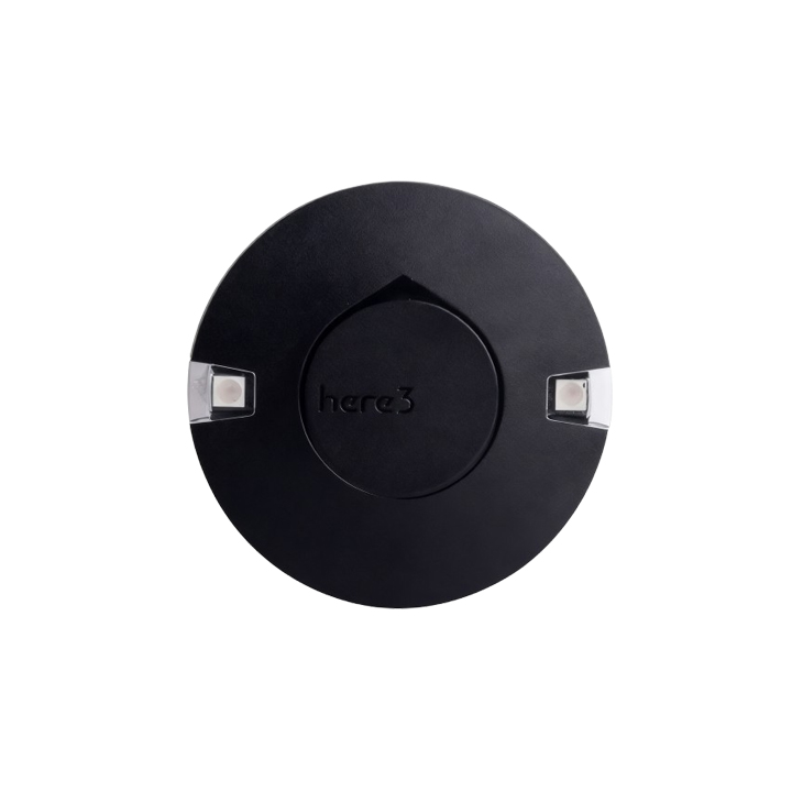
By leveraging advanced RTK modules like the HEX Here3, operators can trust that their autonomous platforms will execute millimeter-accurate surveying grids and return safely, regardless of terrestrial obstructions.
Frequently Asked Questions (FAQ)
Authoritative Industry References
To ensure your navigation architecture aligns with stringent global engineering standards and regulatory compliances, we strongly advise consulting the following organizations:
- Institute of Electrical and Electronics Engineers (IEEE) – The premier professional association publishing foundational peer-reviewed research on MEMS sensor fusion, Kalman filtering algorithms, and aerospace electronic standards.
- The Institute of Navigation (ION) – The world’s leading non-profit professional society dedicated to the advancement of positioning, navigation, and timing (PNT) technologies.
- RTCA (Radio Technical Commission for Aeronautics) – Develops the Minimum Operational Performance Standards (MOPS) required for avionics hardware and integrated navigation systems utilized in advanced aviation.