


In modern aerospace, robotics, and consumer electronics, miniaturization is not merely a design preference; it is a strict operational necessity. The days of relying on bulky, mechanical ring-laser gyroscopes and heavy analog sensors are long gone. Today, the foundational technology driving autonomous navigation, stabilization, and environmental sensing relies entirely on Micro-Electromechanical Systems. However, navigating the component supply chain requires a deep understanding of the silicon structures governing these systems. If you are developing an autopilot system for a commercial drone, choosing the wrong sensor architecture will result in catastrophic navigation drift and mission failure.
From our experience as a leading vtol drone manufacturer, the failure to distinguish between consumer-grade and industrial-grade sensor silicon is the primary reason many UAV startups fail to achieve commercial viability. We do not just purchase these components; we integrate them into high-stress, high-vibration aviation environments. In this comprehensive guide, we will break down the Common Types of MEMS Devices, explaining their physical mechanics, integration parameters, and whether specific architectures are actually worth using in your hardware stack.
Quick Answer: What are the Common Types of MEMS Devices?
The five most Common Types of MEMS Devices utilized in commercial and industrial engineering are Accelerometers (measuring linear motion and gravity), Gyroscopes (measuring angular rotational velocity), Pressure Sensors/Barometers (measuring atmospheric pressure for altitude), Magnetometers (measuring magnetic fields for heading), and Microphones/Acoustic Sensors. When accelerometers, gyroscopes, and magnetometers are packaged together, they form an Inertial Measurement Unit (IMU) or Attitude and Heading Reference System (AHRS), which serves as the central nervous system for autonomous vehicles and robotics.
Table of Contents
- What is a MEMS Device?
- How MEMS Technology Works
- The 5 Common Types of MEMS Devices
- Commercial and Engineering Benefits
- Limitations and Mechanical Realities
- Who Should Use It vs. Who Does Not Need It
- Common Mistakes in Sensor Integration
- Buying Considerations for Industrial Applications
- Expert Recommendation from China Moneypro
- Frequently Asked Questions
What is a MEMS Device?
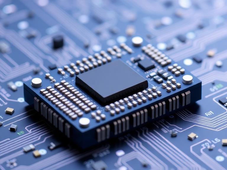
Micro-Electromechanical Systems (MEMS) represent a manufacturing technology that integrates mechanical moving parts and electronic circuits on a single microscopic silicon chip. Using specialized micro-fabrication techniques derived from the semiconductor industry—such as photolithography, wet etching, and deep reactive ion etching—engineers can sculpt microscopic springs, proof masses, and vibrating cantilevers directly into silicon wafers.
Instead of assembling a sensor from individual macroscopic parts, a MEMS device is carved out of a solid block of silicon. The resulting structures are measured in micrometers. In the context of industrial uav solutions, these devices are absolutely essential. They provide the flight controller with real-time, high-frequency data regarding the aircraft’s orientation, acceleration, and altitude, enabling the complex calculus required to keep an unstable aerodynamic frame in the air.
How MEMS Technology Works
The core operating principle of most Common Types of MEMS Devices relies on capacitive sensing or the piezoresistive effect. In a capacitive MEMS sensor, a microscopic mass of silicon (the proof mass) is suspended by tiny silicon springs. Adjacent to this moving mass are fixed silicon plates.
When the device experiences physical acceleration or rotation, inertia causes the suspended proof mass to shift its position relative to the fixed plates. This microscopic movement changes the electrical capacitance between the plates. The integrated Application-Specific Integrated Circuit (ASIC) immediately detects this change in capacitance, amplifies the signal, filters out high-frequency noise, and converts it into a digital signal (typically via SPI or I2C protocols) that a microprocessor can read. This entire mechanical-to-electrical conversion happens thousands of times per second.
The 5 Common Types of MEMS Devices
While the umbrella of micro-electromechanical systems covers everything from inkjet printer nozzles to optical mirrors, the following five categories dominate the sensory input landscape for robotics, consumer electronics, and aviation.
1. MEMS Accelerometers
Accelerometers measure linear acceleration along one, two, or three axes (X, Y, and Z). They detect both dynamic acceleration (movement, shock, vibration) and static acceleration (the continuous pull of Earth’s gravity). In an aircraft, the accelerometer tells the flight controller which way is down, establishing the artificial horizon. Without a highly accurate accelerometer, a commercial fixed wing uav cannot maintain level flight.
2. MEMS Gyroscopes
Gyroscopes measure angular velocity—the rate of rotation around an axis (roll, pitch, and yaw). MEMS gyros rely on the Coriolis effect. They contain vibrating microscopic elements; when the sensor is rotated, the Coriolis force induces a secondary vibration perpendicular to the primary one. The capacitance change resulting from this secondary vibration is directly proportional to the rate of rotation. For platforms like a long range drone with camera, gyroscopes are critical for gimbal stabilization, ensuring blur-free imagery.
3. MEMS Pressure Sensors (Barometers)
These sensors measure atmospheric pressure using a flexible silicon diaphragm equipped with piezoresistors. As atmospheric pressure changes, the diaphragm deflects, altering the electrical resistance. Because atmospheric pressure predictably drops as altitude increases, flight controllers use these devices as altimeters. In most professional situations, a highly calibrated MEMS barometer is what allows a drone to perform precise terrain-following or autonomous altitude holding.
4. MEMS Magnetometers
Often referred to as digital compasses, magnetometers detect the strength and direction of Earth’s magnetic field. They are used to determine the absolute heading of a vehicle. While not entirely mechanical in the traditional MEMS sense (they often use the Hall effect, magneto-resistive, or magneto-inductive principles), they are co-packaged with MEMS sensors to complete the navigational suite.
5. MEMS Inertial Measurement Units (IMUs) and AHRS
In heavy-duty applications, engineers do not use standalone accelerometers or gyros. They use an IMU, which packages a 3-axis accelerometer, 3-axis gyroscope, and often a 3-axis magnetometer into a single silicon package (a 6-axis or 9-axis sensor). When you add a dedicated microprocessor running complex Kalman filtering algorithms to fuse this raw data into usable pitch, roll, and yaw outputs, the device becomes an Attitude and Heading Reference System (AHRS).

China Moneypro MEMS Inertial Measurement Module MOPKT6475
For engineers designing custom flight controllers or autonomous robotics, the MOPKT6475 represents the pinnacle of industrial-grade inertial measurement. This module is a direct, pin-to-pin replacement for the ADIS16475, offering uncompromising stability.
- Real-time measurement of 3-axis angular rate and 3-axis acceleration.
- Built-in full-temperature compensation for stable performance across harsh thermal environments.
- Fast dynamic response suitable for high-speed motion applications.
- SPI interface for seamless communication and integration.
- Direct PCB mounting via industry-standard BGA packaging.
Commercial and Engineering Benefits
The transition to MEMS technology has unlocked capabilities that were physically impossible three decades ago. The primary benefit is SWaP-C optimization (Size, Weight, Power, and Cost). Traditional mechanical gyroscopes weighed several pounds, consumed massive amounts of electricity, and cost tens of thousands of dollars. A modern industrial MEMS IMU weighs a few grams, consumes milliwatts of power, and can be purchased for a fraction of the cost.
This dramatic reduction in weight and power consumption is exactly what made modern drone technology viable. Without MEMS, building an efficient cargo drone solutions platform would be impossible, as the payload capacity would be entirely consumed by heavy navigational hardware.
Limitations and Mechanical Realities
We must exercise commercial and practical judgment: MEMS devices are not flawless. Because the internal structures are microscopic, they are hyper-sensitive to external environmental factors. The two most critical limitations are thermal drift and vibration noise.
As the silicon chip heats up during operation (or due to external weather), the physical properties of the microscopic springs change, causing the sensor’s baseline readings to drift over time. This is known as bias instability. Furthermore, because a fixed wing drones motor generates severe high-frequency vibrations, those vibrations can resonate with the natural frequency of the MEMS proof mass, overwhelming the real motion data with massive amounts of noise (aliasing).
| Advantages (Pros) | Disadvantages (Cons) |
|---|---|
| Ultra-compact footprint and extremely low weight. | Highly susceptible to high-frequency mechanical vibration. |
| Low power consumption extends battery life in mobile systems. | Inherent bias drift over time without external reference corrections. |
| Mass production via silicon wafers lowers unit costs significantly. | Requires complex digital filtering (e.g., Kalman filters) to clean raw data. |
| High shock tolerance (often surviving 10,000g impacts). | Performance degrades rapidly if thermal compensation algorithms are poor. |
Who Should Use It vs. Who Does Not Need It
For commercial users and aerospace engineers: If you are manufacturing a fixed wing drone for photogrammetry or a tactical robotics platform, you must utilize tactical-grade or industrial-grade MEMS IMUs. You require sensors with extremely low bias instability (measured in degrees per hour) and robust factory thermal calibration to ensure the aircraft does not fly off course during extended Beyond Visual Line of Sight (BVLOS) missions.
Who does not need it: If you are building a stationary IoT weather station or a simple smart home device, investing in a high-end AHRS module is a waste of capital. Consumer-grade MEMS sensors (the kind found in smartphones) are perfectly adequate for detecting basic screen orientation or ambient room pressure. Save your budget for the application layer.
Common Mistakes in Sensor Integration
The most devastating mistake we see in UAV manufacturing is the hard-mounting of an IMU directly to a drone frame. If you bolt the sensor directly to carbon fiber near a propulsion motor, the MEMS structure will be subjected to intense resonant frequencies. This ruins the signal-to-noise ratio. You must decouple the sensor using engineered vibration-dampening foam or specialized isolation mounts.
Another frequent error is ignoring magnetic interference. Placing a MEMS magnetometer right next to high-current battery cables or spinning brushless motors will induce massive magnetic deviations. The heading data will be entirely corrupted, leading to the dreaded “toilet-bowl effect” during GPS-assisted loitering.
Buying Considerations for Industrial Applications
When procuring Common Types of MEMS Devices for integration, do not look at the marketing brochure; look at the Allan Variance curves on the datasheet. You must evaluate the In-Run Bias Instability. For industrial applications, you need a gyroscope bias instability of less than 2 degrees per hour. Anything higher is consumer-grade and unsafe for commercial aviation.
Secondly, evaluate the thermal calibration. A reliable manufacturer will place every sensor into a thermal chamber during production and bake a unique temperature compensation matrix directly into the sensor’s firmware. If the sensor lacks hardware-level thermal compensation, your software engineers will spend months trying to fix drifting flight dynamics in code.
| Specification | Consumer Grade (Smartphones, Toys) | Industrial/Tactical Grade (UAVs, Robotics) |
|---|---|---|
| Gyro Bias Instability | 10° to 50° / hour | 0.5° to 2° / hour |
| Thermal Calibration | Basic / Uncalibrated | Full temperature range (-40°C to +85°C) factory calibrated |
| Vibration Rejection | Poor | High (advanced internal dampening and filtering) |
| Cost Profile | $1 – $10 | $200 – $1,500+ |
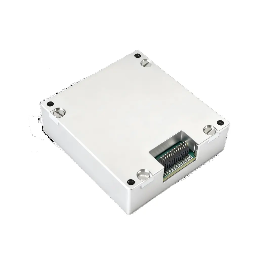
China Moneypro MOPKT-EX9-2-A MEMS Attitude and Heading Reference System (AHRS)
If you are building a vtol cargo drone, raw sensor data is not enough. You need actionable Euler angles. The MOPKT-EX9-2-A handles the intense mathematics required to fuse sensor data, delivering stable attitude and heading outputs even in highly dynamic, magnetically noisy environments.
- High-precision MEMS IMU integrated with proprietary fusion algorithms.
- Built-in magnetometer error ellipsoid model with real-time online calibration.
- Stable and reliable output against high-vibration dynamic environments.
- Strong anti-interference capability, ensuring your platform stays on course.
Expert Recommendation from China Moneypro
In most professional situations, treating MEMS sensors as commoditized afterthought components guarantees an unstable flight platform. We recommend heavily investing in the highest-grade IMU or AHRS module your Bill of Materials (BOM) can support. If you are developing a bvlos fixed wing uav, your aircraft will temporarily lose GPS signaling. When that happens, the aircraft relies entirely on the MEMS IMU for dead-reckoning navigation. If your IMU drifts, your aircraft will crash.
At China Moneypro, we rigorously vet and utilize only full-temperature compensated, industrially calibrated silicon in our flight controllers. We strongly advise engineering teams to abandon bare-chip integration unless they have a dedicated sensor fusion algorithms team. Instead, purchase fully integrated, factory-calibrated AHRS modules to accelerate your time-to-market and guarantee platform safety.
Frequently Asked Questions (FAQ)
An IMU (Inertial Measurement Unit) only provides raw data—specifically, the raw acceleration and angular velocity numbers. An AHRS (Attitude and Heading Reference System) takes that raw data, runs it through an onboard microprocessor using sensor fusion algorithms (like a Kalman filter), and outputs the actual orientation of the vehicle in space (Pitch, Roll, and Yaw).
MEMS gyroscopes drift because integrating angular velocity to find angular position causes small, continuous measurement errors to accumulate over time. Additionally, microscopic changes in the silicon structure due to temperature fluctuations (thermal drift) alter the baseline zero-rate output.
Magnetometers must be calibrated to account for hard-iron and soft-iron interference generated by the drone’s own electronics and frame. This is typically done by rotating the fully assembled drone in a spherical motion across all axes, allowing the flight controller to map the local magnetic distortions and create a calibration offset matrix.
Authoritative References & Industry Standards
To ensure your sensor integration meets stringent global aerospace standards, we recommend reviewing guidelines from the following authoritative bodies:
- Institute of Electrical and Electronics Engineers (IEEE) – Access peer-reviewed papers on MEMS fabrication, sensor fusion algorithms, and Allan Variance testing methodologies.
- National Institute of Standards and Technology (NIST) – Standards and calibration protocols for micro-machined inertial sensors and metrology.
- Federal Aviation Administration (FAA) – Regulatory requirements for avionics safety, redundancy, and navigational accuracy in commercial Unmanned Aircraft Systems (UAS).