


A ten-dollar consumer sensor found in a toy drone operates on fundamentally different physical tolerances than a temperature-compensated, industrial-grade navigation sensor. From our experience in unmanned aerial system integration, cutting corners on your inertial measurement unit is the fastest path to unrecoverable dead-reckoning errors, erratic flight control loops, and mission aborts during satellite signal denial. This guide cuts through the marketing fluff to explain what an IMU does, how industrial sensors function under dynamic operational stress, and how to select the exact hardware grade your platform demands.
Quick Answer: What is an Inertial Measurement Unit?
An inertial measurement unit (IMU) is an electronic device that measures and reports a body’s specific force, angular rate, and sometimes the surrounding magnetic field using an integrated cluster of triaxial accelerometers, gyroscopes, and magnetometers. By sampling these kinematic parameters at high frequencies (typically 200 Hz to 1000 Hz), the IMU delivers raw spatial data to navigation computers, which calculate attitude, velocity, and positional displacement through sensor fusion algorithms such as Extended Kalman Filters (EKF).
Table of Contents
- How an Inertial Measurement Unit Works: Internal Architecture
- Quick Summary: IMU Performance Tiers
- Core Operational Benefits in Industrial Systems
- Inherent Physics Limitations: Bias Drift and Noise
- Who Needs Tactical/Industrial IMUs vs. Consumer Chips
- Hardware Deep Dive: China Moneypro MOPKT-EX9-3 Module
- Technical Comparison: Sensor Classes Across Operational Environments
- Pros and Cons: Standard MEMS vs. Calibrated Industrial IMU Modules
- Critical Integration Mistakes Engineers Make in the Field
- Commercial Buying Considerations and Selection Framework
- Expert Recommendation for Commercial Integrators
- Frequently Asked Questions (FAQ)
- Authoritative References
How an Inertial Measurement Unit Works: Internal Architecture
At its core, an inertial measurement unit tracks motion entirely from internal reference frames without relying on external radio signals, optical tracking, or global satellite constellations. It delivers continuous data across multiple Degrees of Freedom (DOF):
1. Triaxial Accelerometers: These sensors measure specific linear acceleration along the X, Y, and Z spatial axes. When static, they detect the gravitational acceleration vector (1g), providing an absolute reference for pitch and roll calculations. During transit, they measure dynamic acceleration forces generated by propulsion and external environmental turbulence.
2. Triaxial Gyroscopes: Gyroscopic elements measure angular velocity (rotation rate) around the pitch, roll, and yaw axes in degrees per second (°/s). High-performance micro-electromechanical systems (MEMS) use vibrating ring or tuning-fork architectures that generate measurable Coriolis forces proportional to the rotation rate.
3. Triaxial Magnetometers (9-DOF Units): Magnetometers capture the local magnetic field vectors, serving as an electronic compass. In a 9-DOF inertial measurement unit, magnetometer data resolves the yaw axis heading drift that standard gyroscopes cannot natively correct in unassisted dead reckoning.
When raw inertial data streams into an Attitude and Heading Reference System (AHRS) or an autopilot flight controller, mathematical integration occurs. Accelerometer data is integrated once to determine linear velocity and twice to derive relative displacement. Gyroscope data is integrated to derive angular orientation. Because mathematical integration compounds minute sensor errors over time, sensor quality and algorithmic filtering dictate real-world performance.
Quick Summary: IMU Performance Tiers
| Performance Tier | Gyro In-Run Bias Instability | Angle Random Walk (ARW) | Typical Application Profile |
|---|---|---|---|
| Consumer Grade | > 20°/h to 100°/h | > 1.0°/√h | Smartphones, entry-level consumer quadcopters, gaming accessories |
| Industrial Grade | 1.0°/h to 15°/h | 0.10°/√h to 0.30°/√h | Surveying drones, inspection robotics, industrial automated guided vehicles (AGVs) |
| Tactical Grade | 0.1°/h to 1.0°/h | 0.01°/√h to 0.08°/√h | BVLOS autonomous platforms, defense UAS, subsea ROVs, precision LiDAR mapping |
| Navigation Grade | < 0.01°/h | < 0.002°/√h | Commercial aviation airliners, naval submarines, spacecraft guidance |
Core Operational Benefits in Industrial Systems
Integrating an industrial-grade inertial measurement unit provides three decisive advantages that software tricks cannot replicate:
Immunity to Signal Jamming and Spoofing: Global Navigation Satellite Systems (GNSS) operate on low-power radio signals susceptible to atmospheric degradation, urban canyon multipath reflections, and intentional electronic interference. An IMU operates completely passively. In GNSS-denied environments, a calibrated IMU enables dead-reckoning navigation, keeping high-value assets stable and on course until satellite lock re-establishes.
High-Bandwidth Control Loops: Satellite positioning updates at relatively slow rates, typically between 1 Hz and 20 Hz. Dynamic aircraft platforms, such as an electric vtol drone transitioning from vertical hover to forward aerodynamic flight, require stability corrections at rates upwards of 200 Hz to 400 Hz. The high sampling bandwidth of an IMU supplies real-time kinematic feedback to drive flight control surfaces and motor ESCs instantly.
Precise Payload Stabilization: Beyond platform flight dynamics, an IMU powers gimbal stabilization arrays for optical, multispectral, and LiDAR sensors. When deploying a long range drone with camera for infrastructure inspection, sub-degree attitude measurement ensures high-magnification electro-optical payloads remain locked on the target regardless of airframe buffeting.
Inherent Physics Limitations: Bias Drift and Noise
Despite its critical utility, an inertial measurement unit is governed by deterministic and stochastic physical limitations that every engineer must account for:
In-Run Bias Instability: No gyro or accelerometer outputs an absolute zero when stationary. This resting offset (bias) wanders unpredictably over time due to flicker noise in the electronics. Because position calculation requires double mathematical integration of acceleration ($p = \iint a \, dt$), an uncorrected accelerometer bias error grows quadratically with time ($t^2$), while gyro bias error causes position drift that scales cubically ($t^3$).
Thermo-Mechanical Stress: Rapid ambient temperature shifts distort MEMS micro-structures, inducing thermal scale-factor errors and sudden bias shifts. Without internal factory calibration across the operating temperature envelope, an IMU exposed to high-altitude cold will miscalculate platform attitude rapidly.
Vibration Rectification Error (VRE): Asymmetric mechanical resonance from combustion engines, propellers, or industrial machinery can rectify into false DC acceleration signals. Cheap sensors interpret high-frequency vibration as steady linear velocity, throwing the vehicle into aggressive, erroneous trajectory corrections.
Who Needs Tactical/Industrial IMUs vs. Who Does Not Need It
Who needs an industrial-grade IMU: Commercial enterprise operators executing demanding missions. If you deploy a bvlos fixed wing uav beyond visual line of sight, manage automated maritime logistics, or operate a fixed wing drone for photogrammetry demanding centimeter-level direct georeferencing, an industrial IMU module is non-negotiable. In these operational frameworks, sensor drift translates directly into mission failure or physical airframe loss.
Who does not need it: For beginners building educational DIY quadcopters, line-of-sight hobby aircraft, or short-range agricultural rovers with continuous RTK-GNSS lock, a low-cost commercial IMU breakout board is entirely sufficient. Paying for sub-degree per hour bias instability is unjustified when your flight profiles last only ten minutes within clear human visual range.
Hardware Spotlight: China Moneypro MOPKT-EX9-3 Industrial 9-DOF IMU
In most professional situations requiring deterministic navigation under adverse vibration and thermal profiles, integrated multi-axis sensor packages deliver the consistency discrete chips cannot match. The China Moneypro MOPKT-EX9-3 Nine-Degree-of-Freedom Inertial Measurement Unit Module exemplifies industrial-grade engineering optimized for demanding avionics, robotics, and mapping systems.
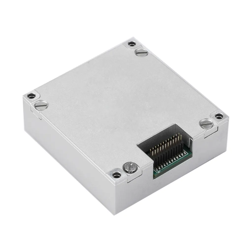
- Measurement Range (Customizable): ±480 °/s
- Zero-Pitch Instability (@ Allan Variance): 0.3 °/h
- Zero Offset Stability (10s Smoothing, 1σ, Room Temp): 3 °/h
- Zero-Level Offset: 15 °/h
- Zero Bias Repeatability: 5 °/h
- Zero Bias Error Across Full Temperature Range: 20 °/h
- Angle Random Walk: 0.15 °/√h
- Bandwidth: 250 Hz
- Cross Coupling: 0.1%
- Scale Factor Nonlinearity: 100 ppm
- Resolution Ratio: 0.0005 °/s
Target Platform Applications:
- UAV flight control arrays and fly-by-wire autopilots
- Autonomous ground vehicles, mining haulage, and warehouse robotics
- Marine navigation, dynamic positioning, and shipborne stabilization
- Industrial motion control, crane monitoring, and factory automation
- Attitude and Heading Reference Systems (AHRS)
- High-precision surveying, mobile mapping, and aerial photogrammetry payloads
Technical Comparison: Sensor Classes Across Operational Environments
| Metric / Parameter | Low-Grade Consumer MEMS | Industrial MEMS (MOPKT-EX9-3 Class) | Tactical Fiber Optic Gyro (FOG) |
|---|---|---|---|
| Gyro Bias Instability | 25.0°/h to 100.0°/h | 0.3°/h to 3.0°/h | 0.01°/h to 0.1°/h |
| Angle Random Walk | > 1.20°/√h | 0.15°/√h | < 0.005°/√h |
| Temperature Calibration | Uncalibrated or rough LUT | Full thermal calibration (-40°C to +85°C) | Precision active thermal modeling |
| Vibration Resistance | Vulnerable to acoustic/motor noise | Integrated mechanical damping & filtering | Extremely high structural immunity |
| Size, Weight & Power (SWaP) | Extremely low (< 2g, < 50mW) | Optimized compact (< 50g, < 1.5W) | Bulky and power-intensive (> 500g, > 10W) |
| Unit Cost Range | $5 to $50 | $500 to $3,500 | $15,000 to $60,000+ |
Pros and Cons: Standard MEMS vs. Calibrated Industrial IMU Modules
| Configuration Class | Key Operational Advantages | Engineering Drawbacks & Trade-offs |
|---|---|---|
| Standard Commercial MEMS |
|
|
| Industrial Calibrated IMU (e.g., MOPKT-EX9-3) |
|
|
Critical Integration Mistakes Engineers Make in the Field
In our testing across multi-rotor, hybrid, and fixed-wing platforms, even high-end sensors underperform when system integration is poorly executed. These are the three most frequent engineering errors:
1. Neglecting Center of Gravity (CoG) Alignment: Mounting the inertial measurement unit far from the aircraft or vehicle’s true center of gravity introduces lever-arm acceleration artifacts. When the vehicle rotates, the offset sensor measures a false centripetal acceleration vector. If your flight computer’s Extended Kalman Filter is not parameterized with the exact geometric lever-arm offset ($[x, y, z]$ offsets), attitude estimation degrades rapidly during aggressive maneuvers.
2. Inadequate Structural Vibration Decoupling: Direct rigid bonding of an IMU to an airframe powered by heavy internal combustion engines—such as those on a heavy lift vtol drone or a hybrid vtol drone—will saturate the internal sensing elements. Integrators must carefully match the durometer rating of silicone isolation mounts to the platform’s primary harmonic excitation frequencies to prevent vibration rectification errors.
3. Unmitigated Electromagnetic Interference (EMI): In 9-DOF modules, internal magnetometers are highly vulnerable to localized electromagnetic interference from high-current ESC power distribution buses, heavy-duty brushless motors, and onboard telemetry transmitters. Placing an IMU within 10 centimeters of an unshielded 12S battery wire turns magnetometer heading fusion into a hazard. Magnetic shielding or physical separation is mandatory.
Commercial Buying Considerations and Selection Framework
When selecting an inertial measurement unit for production integration, evaluate your procurement based on strict mission constraints rather than arbitrary datasheet claims:
| Mission Profile | Required IMU Grade | Critical Specification Thresholds | Recommended Airframe / System Types |
|---|---|---|---|
| Extended BVLOS Inspection & Surveillance | Industrial / Tactical MEMS | Bias Instability < 1.0°/h; Bandwidth ≥ 200 Hz | long range vtol drone, long endurance vtol drone |
| High-Precision Aerial Surveying & LiDAR | Calibrated 9-DOF Industrial IMU | Angle Random Walk ≤ 0.15°/√h; Non-linearity ≤ 100 ppm | commercial fixed wing uav, aerial photogrammetry rigs |
| Tactical Defense & Subsea Navigation | Tactical FOG / High-End MEMS | Bias Instability < 0.1°/h; Full Faraday Shielding | Long-range military UAS, autonomous underwater vehicles (AUVs) |
| Short-Range Line-of-Sight Mapping | Standard Industrial MEMS | Bias Instability < 15°/h; Multi-constellation GNSS pairing | Standard industrial multi-rotors, mapping fixed wing drones |
Expert Recommendation for Commercial Integrators
From our experience in high-end unmanned vehicle engineering, the cost of an inertial measurement unit should always be evaluated relative to the total value of your payload and platform. Installing a twenty-dollar uncalibrated IMU into a multi-thousand-dollar airframe equipped with high-end optical payloads is fundamentally flawed engineering. In most professional situations, the operational risk far outweighs the marginal hardware savings.
For commercial users operating long-range autonomous systems, we recommend deploying factory-calibrated 9-DOF modules with Allan variance-verified bias instability ratings below 1°/h, such as the China Moneypro MOPKT-EX9-3. With a proven 0.3°/h zero-pitch instability, wide 250 Hz dynamic bandwidth, and robust 100 ppm scale factor linearity, it provides the deterministic attitude estimation necessary to navigate safely through signal dropouts and extreme flight envelopes. Treat your IMU as the mission-critical core of your flight computer—because when satellite navigation drops offline, your IMU is the only sensor keeping your aircraft in the sky.
Frequently Asked Questions (FAQ)
Authoritative References
For further technical validation regarding inertial navigation dynamics and standard testing methodologies, refer to the following industry standards organizations:
- IEEE Aerospace & Electronic Systems Society – Standard specification formats and test procedures for inertial sensors (IEEE Std 952 and IEEE Std 1293).
- American Institute of Aeronautics and Astronautics (AIAA) – Guidance, navigation, and control (GNC) technical resources and flight dynamics standards.
- National Institute of Standards and Technology (NIST) – Research publications on precision measurement, MEMS characterization, and Allan variance noise profiling.