Amplifier Redefined: Deep Dive into the 50W Power Amplifier Performance
n
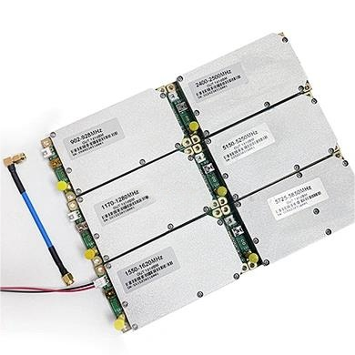
In the demanding world of RF engineering, the 50W power amplifier stands as a cornerstone of reliable signal transmission across the 6000-7000MHz band. This device, designed for high-performance operation, requires meticulous attention to technical specs to ensure seamless integration into modern communication systems. Whether you are deploying radar, satellite, or point-to-point links, understanding the precise parameters of this amplifier is crucial for optimizing system efficiency. This article explores every facet of the unit, from power delivery to protection mechanisms, providing a comprehensive guide for engineers and system integrators.
n
Core Technical Specifications: 50W Power Amplifier Performance Metrics
n
At the heart of any amplifier lies its technical backbone. The following table details the critical parameters that define the 50W power amplifier’s operational envelope. This data is essential for validating system compatibility and predicting performance under varying conditions.
n
| Test Item | Indicator | Remarks |
|---|---|---|
| Frequency | 6000-7000 MHz | Full band operation |
| Working Voltage | 32V | Range 28-34V |
| Maximum Output Power | 47 ± 0.5 dBm | Peak capability |
| Operating Current | 7A | @50W typical output |
| Controllable Output Power | 30W – 50W | ALC adjustable range |
| ALC Power Regulation Range | ≥ 3 dB | Automatic level control |
| Gain | 47 ± 1.0 dB | Peak to peak value |
| Intraband Fluctuation | ± 2 dB | Lasts for 1 min without damage |
| Maximum Allowable Input Power | ≥ +10 dBm | Standard network output -10 dBm |
| Input Voltage Standing Wave Ratio | ≤ 1.50 | No power on, standard network output -10 dBm |
| Output Voltage Standing Wave Ratio | ≤ 1.50 | Power on, dual directional coupler test |
| Low Temperature Startup | Works normally | Monitoring functional |
| High and Low Temperature Test | @50W typical | Cold start & monitoring OK |
| Gain Stability | ± 1.5 dB | @ -10°C to +55°C |
| Power Stability | ± 1.5 dB | @ -10°C to +55°C |
| Power Supply Requirement | ≥ 9A @ +36 Vdc | Continuous wave output 100W capability |
n
Power Supply, Control Interface, and Connectors
n
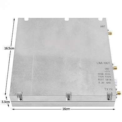
The amplifier integrates a sophisticated power and control interface to manage its high-performance operation. The 7W2 connector provides both power and control lines. Understanding this pinout is critical for proper system integration and monitoring.
n
| Connector Pin | Signal | Description |
|---|---|---|
| A1 | VCC +28V | Main power input |
| A2 | GND | Ground reference |
| 1 | TEMP_AL | Temperature detection, high-level alarm, low-level cancellation |
| 2 | RUN | High-level operation indication |
| 3 | VSWR_AL | Standing wave alarm, high-level alarm, low-level cancellation |
n
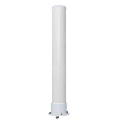
The RF output is delivered via a robust N-Female connector, ensuring low loss and high durability in field installations. This choice simplifies integration with standard cabling and test equipment.
n
Advanced Protection and Monitoring Features for the 50W Power Amplifier
n
Reliability in the field hinges on intelligent protection mechanisms. This 50W power amplifier includes a suite of safeguards to prevent damage from thermal stress, load mismatch, and signal anomalies. The module employs temperature compensation to maintain linearity across its operating range. Overtemperature and standing wave protection actively monitor internal conditions, automatically reducing output or shutting down the amplifier to avoid catastrophic failure. These features extend the lifespan of the device and protect downstream components.
n
Built-in Signal Source and Visual Indicators
n
To simplify testing and calibration, the amplifier is equipped with a built-in high-speed noise modulation signal source. This allows for rapid performance verification without external signal generators. Visual status is provided by three front-panel LED indicators: a green POWER light confirms supply voltage, a green RUN light indicates active amplification, and a red VSWR light provides an immediate visual alert for standing wave issues, enabling quick diagnostic response. This integrated design reduces setup time and enhances operational awareness.
n
Conclusion: Maximizing Performance with the 50W Power Amplifier
n
The 50W power amplifier model MOP-PA-6/7G-50W represents a robust solution for high-frequency applications in the 6-7 GHz range. Its precise specifications, including a maximum output of 47 dBm and an ALC-adjustable range from 30W to 50W, provide the flexibility needed for demanding communication systems. With comprehensive protection features, a clear control interface, and integrated monitoring, this amplifier is engineered for both performance and longevity. By adhering to these technical parameters, engineers can confidently deploy this device, ensuring reliable, high-power transmission in their RF networks.