The Ultimate Guide to the High-Performance Dual Band Diplexer
nn
In the intricate world of radio frequency (RF) engineering, signal clarity and band separation are paramount. When you need to combine or split two distinct frequency paths without sacrificing performance, a specialized component is essential. Enter the dual band diplexer, a device engineered to handle the demanding requirements of modern indoor RF systems. This article dives deep into a specific model designed for the 763-775MHz and 793-805MHz frequency ranges, a high-power solution that sets a new standard for reliability and efficiency.
nn
Understanding the Dual Band Diplexer Core Design
nn
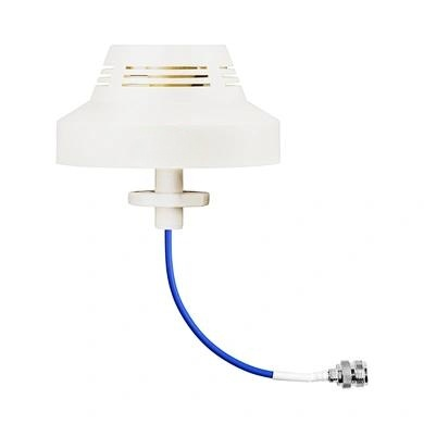
At its heart, this dual band diplexer is a passive RF component that enables a single antenna or cable to be used for two separate frequency bands. The unit we are examining expertly manages the 763-775 MHz and 793-805 MHz ranges. Its design is a testament to precision engineering, ensuring that signals within each band are transmitted with minimal loss while maintaining exceptional isolation between the paths. This makes it a critical core component for distribution systems in buildings, stadiums, and other indoor environments where capacity and coverage are critical.
nn
Superior Electrical Performance of the Dual Band Diplexer
nn
When spec’ing an RF solution, electrical specifications are the ultimate benchmark. This dual band diplexer offers top-tier performance metrics that guarantee high-fidelity signal handling. Let’s break down the key electrical characteristics that make this device a standout choice:
nn
Low Insertion Loss and Excellent VSWR
n
With an insertion loss of less than 2.5 dB, this dual band diplexer ensures that the signal strength on the desired path remains strong and clear. This low-loss characteristic is critical for maintaining system link budgets, especially over longer cable runs. Furthermore, the Voltage Standing Wave Ratio (VSWR) is better than 1.3:1, indicating an excellent impedance match that minimizes reflected power and maximizes power transfer to the antenna or next device.
nn
Industry-Leading Isolation and Rejection
n
One of the most impressive specifications is the port isolation and out-of-band rejection, both of which reach a staggering 70 dB. This performance effectively “brick walls” any signals from one band interfering with another. For the dual band diplexer, this means that signals in the 763-775 MHz band will not leak into the 793-805 MHz path, and vice versa. This level of separation is essential for high-capacity systems where even a small amount of crosstalk can degrade performance.
nn
High Power Handling and Mechanical Durability
nn
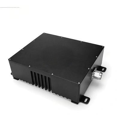
As a high-power RF device, this dual band diplexer is built to handle substantial energy without overheating or performance degradation. The unit boasts a rated power handling capacity of 10 watts (10W), making it suitable for both base station and distributed antenna system (DAS) applications. The robust mechanical design complements this electrical brawn. The device features standard 50Ω impedance matching and comes equipped with premium N-Female (N-F) connectors, ensuring full compatibility with industry-standard cabling. Its compact form factor and mounting hole fixation design allow for secure, clean installations. The durable black housing ensures the device can withstand the rigors of an indoor environment.
nn
Environmental Resilience and Operational Range
n
Reliability in varying conditions is non-negotiable for mission-critical systems. This dual band diplexer is engineered to operate within a wide temperature range of -20°C to +65°C and can tolerate humidity levels from 5% to 97%. This resilience ensures stable, reliable performance in diverse indoor environments, from climate-controlled data centers to unventilated equipment closets or outdoor shelters.
nn
Detailed Specifications of the Dual Band Diplexer
nn
To provide a complete technical overview, the following table displays the precise specifications for this high-performance component.
nn
| Parameter | Value |
|---|---|
| Frequency Range | 763-775 MHz / 793-805 MHz |
| Insertion Loss | < 2.5 dB |
| Isolation | 70 dB |
| VSWR | < 1.3:1 |
| Rejection | 70 dB |
| Power Handling | 10 Watts |
| Impedance | 50 Ω |
| Connectors | N-Female (N-F) |
| Mounting Type | Mounting Holes |
| Housing Color | Black |
| Operating Temperature | -20°C to +65°C |
| Operating Humidity | 5% to 97% |
| Application Environment | Indoor |
nn
Applications and Conclusion for the Dual Band Diplexer
nn
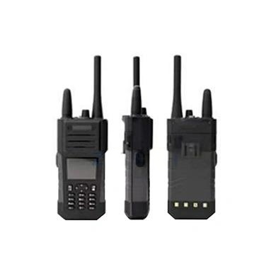
The versatility of this dual band diplexer makes it an ideal choice for numerous applications. It is widely deployed in mobile communication systems (such as 4G and 5G indoor coverage), private network communication (for public safety or utilities), and signal relay systems. Its robust design ensures an efficient, stable band separation solution for any RF system requiring high isolation and low loss. In summary, this dual band diplexer delivers professional-grade electrical performance and mechanical durability. Its ability to provide superior isolation and low insertion loss in a compact, high-power package makes it an indispensable tool for RF engineers seeking to optimize their indoor network infrastructure. Whether you are upgrading a legacy system or building a new high-density network, this component stands ready to deliver unwavering performance.