🚨 Industry Pain Points
In modern UAV and airborne gimbal systems, users often face several technical challenges:
- Difficulty maintaining accurate attitude information during continuous gimbal rotation
- Complex alignment procedures between main inertial navigation and gimbal frame
- Installation errors between main INS and gimbal structure affecting accuracy
- Limited support for dynamic alignment during flight
- Poor decoupling between gimbal frame and aircraft motion
- Inaccurate measurement performance in complex flight conditions
These challenges reduce system stability, measurement accuracy, and operational efficiency.
⚙ Product Advantages
Our MEMS inertial measurement solution is designed to overcome these challenges:
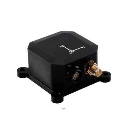
- ✔ MEMS inertial measurement unit for high-precision attitude sensing
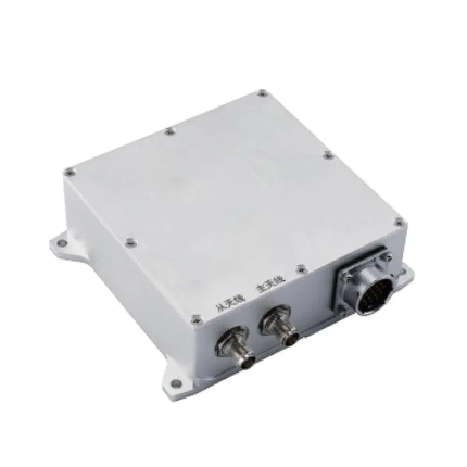
- ✔ Receives data from main inertial navigation, GNSS, and frame angle sensors
- ✔ Supports installation inside the gimbal with frame-following operation
- ✔ Supports transfer alignment during continuous gimbal rotation
- ✔ Online compensation for installation offset between main INS and gimbal frame
- ✔ Automatic calibration of MEMS INS and frame angle relationship
- ✔ Decoupled attitude output for internal and external gimbal base
- ✔ High stability and reliability in dynamic flight environments
🚁 Product Applications
This system is widely used in high-precision airborne platforms:
- UAV gimbal stabilization systems
- Electro-optical payload systems (EO/IR gimbals)
- Airborne reconnaissance systems
- Aerial mapping and surveying platforms
- Target tracking and monitoring systems
- Navigation and attitude measurement systems
Application Fields:
- Navigation
- Control
- Measurement
⭐ Why Choose Us
- High-precision MEMS inertial technology
- Designed specifically for gimbal and payload applications
- Supports continuous rotation alignment
- Automatic calibration and installation compensation
- Stable performance in dynamic environments
- Easy integration with UAV and airborne systems
- Professional customization support available
We provide reliable and high-performance inertial navigation solutions for professional UAV and airborne payload systems.
❓ Frequently Asked Questions (FAQ)
Q1: Does the system support continuous gimbal rotation?
Yes, it supports transfer alignment during continuous rotation.
Q2: Can installation errors be compensated automatically?
Yes, the system supports online compensation for installation offsets.
Q3: What data sources does the system support?
It supports main INS data, satellite navigation data, and frame angle data.
Q4: What applications is this product suitable for?
It is suitable for navigation, control, and measurement applications.
Q5: Can the system output decoupled attitude information?
Yes, it outputs decoupled attitude data for both internal and external gimbal bases.
| Parameter | unit | fundamental form | A mould | B mould | |||
|
The onboard main inertial navigation system provides the navigation information required for alignment transfer. |
Aerial positioning accuracy (RMS) | path angle | ° | 0.1 | 0.3 | 0.1 | |
| Pitch Angle / Roll Angle | ° | 0.05 | 0.2 | 0.05 | |||
| Position Precision (RMS) | horizontal | m | 1.5 | 1.5 | 1.5 | ||
| altitude | m | 3 | 3 | 3 | |||
| Speed Precision (RMS) | m/s | 0.1 | 0.2 | 0.08 | |||
|
gyroscope |
measuring range | ° /s | ±400 | ±300 | ±300 | ||
| Zero offset stability (10-second smoothing, 1σ, room temperature) | ° /h | 1 | 5 | 0.05 | |||
| Full-temperature zero-drift variation (10-second smoothing, RMS, variable temperature) | ° /h | 5 | 20 | 2 | |||
| Zero bias repeatability | ° /h | 5 | 10 | 1 | |||
| random walk | ° / √ h | 0.03 | 0.15 | 0.02 | |||
| tape width | Hz | 400 | 250 | 200 | |||
| Nonlinear scaling factor | ppm | 100 | 100 | 100 | |||
| Scale factor repeatability | ppm | 100 | 100 | 100 | |||
| cross coupling | % | 0.1 | 0.2 | 0.1 | |||
|
accelerometer |
measuring range | g | ±10 | ±10 | ±10 | ||
| Zero offset stability (10-second smoothing, RMS, room temperature) | mg | 0.05 | 0.05 | 0.05 | |||
| Full-temperature zero-drift variation (10-second smoothing, RMS, variable temperature) | mg | 2 | 2 | 2 | |||
| Zero bias repeatability | mg | 0.2 | 0.2 | 0.2 | |||
| tape width | Hz | 250 | 250 | 250 | |||
| Scale factor repeatability | ppm | 500 | 500 | 500 | |||
| cross coupling | % | 0.1 | 0.1 | 0.1 | |||
| Data update rate | Hz | 200 (navigation data output) 4000 (gyroscope data output) | |||||
| voltage | V | 5±0.5 | |||||
| power dissipation | W | ≤ 2 | |||||
| working temperature | ℃ | -45~80 | |||||
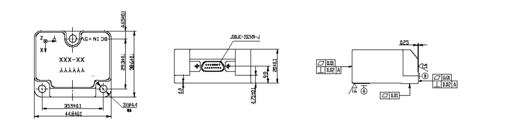
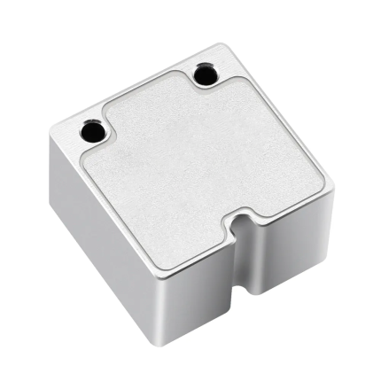
| size | mm | 44.8*38.6*20 | |||||
| weight | g | ≤ 55 | |||||
|
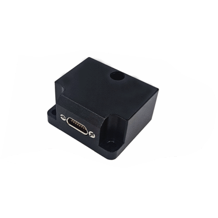
Interface |
—— |
1 RS-422 channel (navigation data output)
1 RS-422 channel (high-frequency gyro output) 1 RS-422 channel (Transfer Alignment Input) 1-channel PPS input |
|||||