
Enhanced Performance with Advanced RF Power Amplifier Technology
n
In the rapidly evolving landscape of wireless communications, the demand for reliable, high-power RF amplification has never been greater. Whether you are deploying IoT networks, satellite links, or industrial telemetry systems, the RF power amplifier at the heart of your transmitter determines overall system performance. The device described here represents a breakthrough in compact, high-efficiency amplification, covering multiple critical frequency bands while maintaining exceptional linearity and output power. Understanding its specifications is essential for engineers seeking to optimize link budgets and ensure regulatory compliance.
n
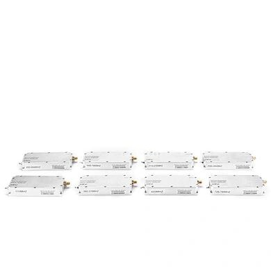
This RF power amplifier unit is engineered to deliver robust performance across five distinct frequency ranges, making it highly versatile for both sub-GHz and GHz applications. Its ability to produce +43dBm (20 watts) of saturated output power with a gain of 45dB ensures strong signal propagation even in challenging environments. The inclusion of ultra-wideband coverage from 428MHz to 5900MHz means a single amplifier can serve multiple protocols, reducing component count and system complexity.
nn
Detailed Specifications and Performance Metrics
n
The following table presents the complete electrical, mechanical, and environmental parameters, ensuring you have all the data needed for system integration. Every specification has been validated to guarantee consistent operation under stated conditions.
nn
| Parameter | Value |
|---|---|
| Frequency Range | 428-438 MHz / 902-928 MHz / 1560-1610 MHz / 2400-2500 MHz / 5500-5900 MHz |
| Maximum Output Power (Pout) | ≥ +43 dBm |
| Gain | 45 ± 1 dB |
| Gain Ripple | ≤ ±1 dB |
| Voltage Standing Wave Ratio | ≤ 1.5:1 |
| Spurious Emission (9 kHz – 1 GHz) | ≤ -36 dBm / 30 kHz |
| Spurious Emission (1 GHz – 12.75 GHz) | ≤ -30 dBm / 30 kHz |
| Maximum Input Power | +10 dBm |
| Operating Voltage | DC +28 V |
| Operating Current | ≤ 3.5 A |
| Power Connector | VH3.96-2PIN |
| RF Connector | SMA-KFD, 50 Ω |
| Data Interface | XH2.54-4PIN |
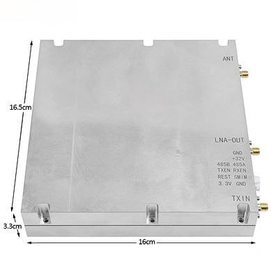
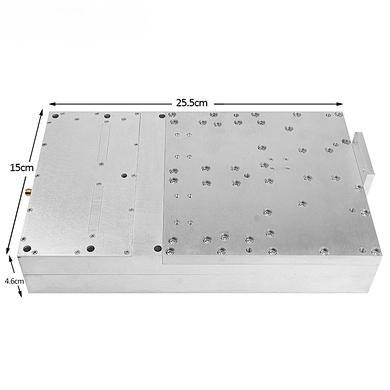
| Dimensions | 165 × 45 × 19 mm |
| Operating Temperature | -10 to +55 °C |
| Operating Humidity | 5% to 95% (non-condensing) |
| Storage Temperature | -25 to +65 °C |
nn
Key Performance Characteristics of This RF Power Amplifier
n
Beyond the raw numbers, several attributes define the usability of this RF power amplifier. The gain flatness of ±1 dB across the entire operating bandwidth ensures minimal signal distortion, critical for modulated waveforms. The low VSWR of 1.5:1 simplifies impedance matching with antennas and filters, reducing reflected power and protecting the amplifier stage. Spurious emissions are suppressed well below regulatory limits, facilitating certification in most jurisdictions.
n
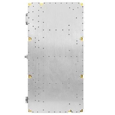
The power supply requirements are straightforward: a single +28V DC rail at up to 3.5A. This allows integration with standard industrial power supplies or battery systems. The compact form factor (165mm × 45mm × 19mm) enables installation in tight enclosures, while the SMA-KFD connector provides a reliable, 50-ohm interface for RF cabling. The inclusion of a data interface (XH2.54-4PIN) suggests provisions for monitoring or control, adding a layer of system intelligence.
nn
Optimizing Your Wireless System with This RF Power Amplifier
n
When designing a high-performance transmitter, the choice of RF power amplifier directly influences coverage area, data rate, and reliability. This module excels in applications where multiple frequency bands must be supported without redesigning the RF front end. For example, a single unit can handle L-band satellite signals, ISM-band industrial links, and 5.8 GHz video backhauls simultaneously if paired with appropriate bandpass filters.
n
Engineers will appreciate the rigorous specification of critical parameters. The 45dB gain allows the amplifier to be driven by low-power transceivers, simplifying the driver stage design. The maximum input power of +10dBm provides a safe operating margin, preventing damage from accidental overdrive. The wide operating temperature range and high humidity tolerance make it suitable for outdoor or unconditioned environments.
nn
Integration and Testing Guidelines
n
For optimal performance, ensure the power supply can deliver 3.5A continuously with low ripple. A linear regulator or high-quality switching supply with adequate filtering is recommended. The SMA-KFD connector should be torqued to the manufacturer’s specification to maintain low insertion loss. When testing, verify gain and output power using a spectrum analyzer with appropriate attenuation to protect the instrument from the +43dBm output.
n
The VSWR specification of 1.5:1 implies that the amplifier can tolerate slight impedance mismatches, but for maximum reliability, use an antenna or load with a return loss better than 14dB. The spurious emission limits guarantee compliance with most spectrum regulatory bodies, but final system certification should always be performed in the intended configuration.
nn
Conclusion: The Versatile, High-Power Solution
n
This RF power amplifier stands out as a highly capable building block for demanding wireless systems. Its multi-band coverage, high output power, and excellent linearity, combined with a rugged mechanical design, make it a top choice for engineers who value both performance and reliability. By carefully integrating this amplifier according to the provided specifications, you can achieve robust, interference-free communications across a wide range of frequencies and applications. Whether upgrading an existing system or designing from scratch, this amplifier delivers the power and precision your project requires.