
Enhancing Signal Reach: The Power of a High-Performance RF Amplifier
nn
In the world of wireless communications, signal integrity is everything. Whether you are working on a telecommunications infrastructure, military radar system, or a specialized IoT network, maintaining a strong and clean signal over long distances is non-negotiable. A high-power amplifier is not just a component; it is the backbone of a reliable transmission chain. When you need to boost a weak signal without adding noise or distortion, understanding the technical backbone of your equipment is critical. This guide dives deep into the specifications of a robust RF amplifier designed for demanding applications, ensuring you know exactly what to look for when optimizing your system.
nn
Core RF Technical Parameters: What to Look For
nn
Before integrating any amplifier into your system, you must verify its core specifications. The device detailed here operates across a critical frequency range, making it suitable for modern high-bandwidth applications. The saturated power output and gain figures indicate a device capable of driving antennas effectively while maintaining the necessary edge for signal clarity. Below, we break down every essential parameter to help you evaluate its performance fit.
nn
Frequency Range and Power Specifications
nn
The amplifier covers a dual-band operational window, ensuring flexibility across different standards. The high gain value minimizes the need for multiple amplification stages, reducing system complexity and potential failure points. In-band flatness, while a crucial metric for signal consistency, is detailed alongside other critical electrical characteristics in the table below. This ensures a clean, predictable output across the entire working spectrum.
nn
| Parameter | Technical Value |
|---|---|
| Working Frequency | 3800-4400 / 4400-5000 MHz |
| Saturated Power Output | 43±1 dBm (Approx. 20W) |
| Gain | 43±2 dB |
| In-band Flatness | ≤ ±1.5 dB (Typical) |
| Input / Output VSWR | ≤1.5:1 |
| Out-of-Band Spurs | 9kHz-1GHz: ≤ -36 dBm/30kHz 1GHz-12.75GHz: ≤ -30 dBm/30kHz |
| Maximum No-Damage Input | +10 dBm |
| Operating Voltage | DC +28V |
nn
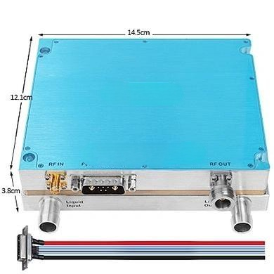
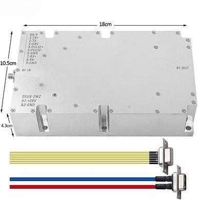
Interfaces and Mechanical Design
nn
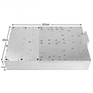
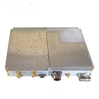
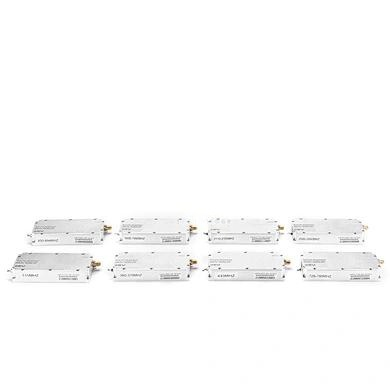
Connectivity and physical integration are often overlooked but are vital for deployment success. This amplifier uses SMA-KFD female connectors on the RF ports, a standard choice for high-frequency applications requiring secure, low-loss connections. The monitoring and power interfaces utilize feed-through capacitors, which help filter noise from the DC supply line, further enhancing signal purity. The compact mechanical footprint allows for easy mounting in chassis or rack-mount systems where space is at a premium.
nn
| Component | Specification |
|---|---|
| RF Input / Output Connectors | SMA-KFD (Female) |
| Power Supply Interface | Feed-through Capacitor |
| Monitoring Interface | Feed-through Capacitor |
| Amplifier Dimensions | 135mm x 67mm x 20mm |
nn
Environmental Resilience and Operating Conditions
nn
Reliability in the field is determined by how well a device withstands real-world conditions. This RF amplifier is engineered for stability across a wide temperature range and maintains performance in humid environments, provided no condensation occurs. The storage temperature tolerance further ensures the device remains safe during transport or periods of inactivity. These factors make it a robust choice for both indoor base stations and outdoor enclosures with climate control.
nn
| Environmental Parameter | Operating Range |
|---|---|
| Operating Temperature | -10°C to +55°C |
| Relative Humidity | 5% to 95% (Non-condensing) |
| Storage Temperature | -25°C to +65°C |
nn
Conclusion: Making an Informed Choice for Your RF Technical Parameters
nn
Selecting an amplifier is about matching your system requirements with the device’s proven capabilities. The unit described here offers a balanced profile of high gain, excellent linearity, and robust construction. By paying close attention to the RF technical parameters such as VSWR, spurious emission limits, and thermal management specifications, you can achieve a link budget that meets your coverage goals. Whether you are upgrading an existing network or building a new point-to-point link, these specifications provide a solid foundation for a successful deployment. Always cross-check the RF technical parameters in the tables above with your system’s needs to ensure optimal performance and longevity.