Ultimate Guide to the Tri Band Power Amplifier with Signal Generator Integration
nn
In the demanding world of professional communication and electronic systems, the need for a single, robust, and intelligent RF solution has never been greater. This high-performance tri band power amplifier, integrated with a signal generator module, represents a leap forward in customizable RF technology. Designed to deliver exceptional power and pristine signal quality, this unit is the cornerstone for multi-band systems, electronic countermeasures, and communication relays. With its software-controlled power, advanced monitoring, and rugged design, it provides a flexible and reliable platform for the most challenging applications. This article explores the remarkable capabilities, detailed specifications, and intelligent features of this revolutionary amplifier, emphasizing why it stands out as the premier choice for professionals seeking a customizable RF solution.
nn
Core Specifications and Performance of the Tri Band Power Amplifier
nn
The foundation of this amplifier’s excellence lies in its carefully engineered parameters. It is not just a simple power booster; it is a precision instrument that ensures stable, uniform, and clean signal amplification across multiple bands. Below is a detailed breakdown of its essential performance characteristics.
nn
| Parameter | Value | Remark |
|---|---|---|
| Working Frequency | Customizable | Configured to specific requirements |
| Output Power | 100W | Maximum rated output |
| Operating Voltage | 28V | Range: 24-36V |
| Conversion Efficiency | ≥42% | At 100W output |
| Adjustable Output Power | 10W ~ 100W | Software-controlled power level |
| ALC Power Adjustment Range | ≥20dB | Voltage-controlled attenuation |
| Gain | 50 ± 1.0 dB | Ensures consistent amplification |
| In-band Fluctuation | ≤ 2.5 dB | Peak variance across the band |
nn
Advanced Signal Purity and Environmental Durability
nn
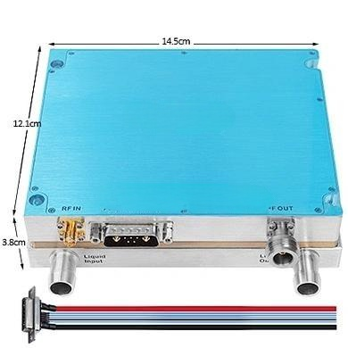
Beyond raw power, the integrated DDS and ALC technologies provide superior control over signal quality. Spurious emissions are kept to a minimum, ensuring compliance with stringent RF standards. Furthermore, the amplifier is built to perform reliably in extreme conditions, from freezing cold to high heat, maintaining stable gain and power output. The following table details these crucial metrics.
nn
| Parameter | Value / Condition | Remark |
|---|---|---|
| Spurious Emissions (In-band) | ≤ -15 dBm / 1 MHz | Measured at max output power with CW signal |
| Spurious Emissions (Out-of-band: 9KHz-1GHz) | Not higher than normal noise floor | Ensures clean spectrum usage |
| Spurious Emissions (1G – 12.75 GHz) | Not higher than normal noise floor | High-frequency purity |
| Max Allowable Input Power | ≥ +10 dBm | Lasts 1 minute without damage |
| Input VSWR | ≤ 1.35 | With +28V, standard network output -10dBm |
| Output VSWR | ≤ 1.35 | With power on, dual directional coupler test |
| Working Environment Temp | -10°C ~ +65°C | Low temp startable, monitoring works normally |
| Gain Stability | ± 1.5 dB | @ -40°C ~ +65°C |
| Power Stability | ± 1 dB | @ -40°C ~ +65°C |
| Power Requirements | ≥ 8.5A @ +28Vdc | For CW output at 100W |
nn
Intelligent Monitoring and Comprehensive Alarms
nn
The rack-mounted version with a touch screen elevates this tri band power amplifier to a smart system. It offers real-time monitoring and a suite of configurable alarms to protect the module and the connected equipment. Users can set and query numerous parameters for complete system awareness. The following table outlines the sophisticated monitoring capabilities.
nn
Amplifier Part: Setting Parameters
nn
| Function | Description | Remark |
|---|---|---|
| Amplifier Switch | Turn the amplifier on or off | Master control |
| Alarm Switch | Enable and disable all alarm functions | Flexible operation |
| Downlink Power Control | Set max output power (range ≥20dB). Adjust between high, medium, and low power levels. | Precise power management |
| Amplifier Over-Temp Alarm | Set high-temp shutdown threshold. Auto shutoff at 85°C; auto-restore at 65°C. | Thermal protection |
| Amplifier Overpower Alarm | Triggers when actual power is 2dB above ALC start control threshold. | Protects against output spikes |
| Amplifier Standing Wave Alarm | Auto turns off amplifier when VSWR > 4. | Antenna mismatch protection |
| Amplifier Overcurrent Alarm | Auto turns off amplifier when current exceeds 12A. | Short-circuit safety |
| Amplifier Under-Power Alarm | Displays alarm when detected power is less than 33 dBm. | Low output warning |
| Amplifier Overvoltage Alarm | Auto shuts down if voltage exceeds 32V. | Input surge protection |
| Amplifier Undervoltage Alarm | Monitors amplifier voltage for lows. | Stability monitoring |
nn
Amplifier Part: Query Parameters
nn
| Parameter | Description | Details |
|---|---|---|
| Amplifier Switch Status | Queries the ON/OFF state of the amplifier | Reflects current operational status |
| Downstream Output Power Level | Detects output power value | Range: (Pomax+2, Pomax-20). Accuracy: Pout ±1dB |
| Downward Standing Wave Ratio | Measures load matching | Normal: 1.2. Mismatch: 4.0 |
| Temperature Query | Detects internal module temperature | Range: -40°C ~ +100°C. Error: ±3°C |
| ALC Value Query | Displays the actual set ALC value | Directly reflects user setting |
| Voltage Detection | Measures module working voltage | Real-time voltage readout |
| Current Detection | Measures module operating current | Real-time current readout |
nn
Versatile Signal Generator Settings and Interface
nn
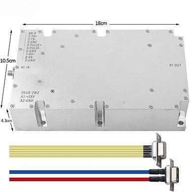
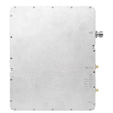
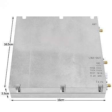
The integrated signal generator offers three distinct frequency setting modes for ultimate flexibility, from single fixed frequencies to complex sweeps and multi-segment configurations. The module communicates via a standard RS485 interface, while physical connections are handled through robust N-Female RF and 7W2 power connectors, complete with front-panel LED indicators for power, run, and alarm status.
nn
| Category | Feature | Specification |
|---|---|---|
| Frequency Setting Mode 1 | Single Fixed Frequency Point | Any frequency within range, accuracy 1M, max bandwidth 500M, max 6G |
| Frequency Setting Mode 2 | Broadband Frequency Sweep | Configurable frequency, interval, and step |
| Frequency Setting Mode 3 | Sub-Frequency Segments | Set any 4 sub-segments within bandwidth, incremented |
| Module Communication Protocol | RS485 | Interface: +28V (Pin 7), GND (Pin 2); 1: 485A, 2: 485B |
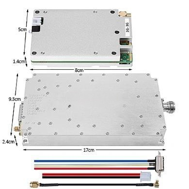
| RF Output Connector | N-Female | Standard, robust RF connection |
| Indicators | 3 LED Lights | POWER (Power), RUN (Running), ALARM (Alarm) |
nn
Conclusion: The Indispensable Tri Band Power Amplifier
nn
This integrated module is far more than a simple amplifier; it is a sophisticated and intelligent RF system core. By combining a powerful tri band power amplifier with a flexible signal generator and comprehensive monitoring, it provides an all-in-one solution that is both powerful and safe. Its customizable frequency, software-controlled power, and robust protective features make it an ideal choice for engineers and system integrators who demand the highest level of performance and reliability. Whether for advanced research, critical communication networks, or electronic defense systems, this customizable RF solution delivers the power, purity, and intelligence required to succeed in the most demanding environments. Its design philosophy focuses on giving the user complete control and peace of mind, making it the definitive choice for any application requiring a high-performance, integrated amplifier.