Unlock a New RF Experience: Why You Deserve This Artifact
n
In today’s rapidly evolving technological landscape, the performance of RF equipment directly dictates work efficiency and outcomes across countless industries. If you’ve been struggling to find a device that combines high performance with unwavering stability, look no further. The Ultra-wideband 700-6000MHz 50W power amplifier integrated with a DDS signal generator, complete with a heat sink and cooling fan, is the definitive solution. This module redefines what’s possible in radio frequency work. Its N-F connector PA ensures superior electrical performance and mechanical stability, delivering exceptionally low signal loss and a reliable connection that keeps your data flowing unimpeded. The built-in DDS generator stands as the core highlight, offering powerful and precise frequency synthesis. Whether you’re conducting complex scientific research or rigorous communication tests, it generates a stable, accurate signal source with ease. The high-stability 50W amplifier performs flawlessly across the ultra-wide 700-6000MHz band, maintaining consistent 50W power output for long-distance transmission or high-strength signal applications. Safety is paramount, with over-temperature protection that automatically shuts down the device when temperatures exceed 85°C, resuming operation at 65°C to extend equipment life. The integrated heat sink and cooling fan work in tandem to keep the module cool under sustained heavy loads. Additional monitoring and alarm features—covering overcurrent, overvoltage, and undervoltage—provide comprehensive protection. Whether for research institutions, communication firms, or electronic engineering professionals, this module elevates your work to new heights. Don’t miss out—get it in your kit and start a new journey of efficient, stable RF operation.
nn
Key Specifications and Parameters
n
Understanding the technical excellence of this module is crucial for selecting the right equipment. Below, we detail the core specifications to help you evaluate its performance.
nn
General and Power Specifications
n
| Parameter | Value | Unit | Remarks |
|---|---|---|---|
| Operating Voltage | 28 | V | 24-30V range |
| Conversion Efficiency | ≥42 | % | Typical at 50W |
| Controllable Output Power | 10~50 | W | Software set power level |
| ALC Power Adjustment Range | ≥10 | dB | |
| Voltage Controlled Attenuation Gain | 47±1.0 | dB | |
| In-band Fluctuation | ≤2.5 | dB | Peak-to-peak |
nn
RF Performance and Environmental Specifications
n
| Parameter | Value | Unit | Remarks |
|---|---|---|---|
| Spurious Emission (In-band) | ≤-15 | dBm/1MHz | Measured with center frequency + CW signal at max power |
| Spurious Emission (Out-of-band 9KHz~1GHz) | No higher than normal noise floor | dBm | |
| Spurious Emission (Out-of-band 1G~12.75GHz) | No higher than normal noise floor | dBm | |
| Maximum Allowable Input Power | ≥+10 | dBm | Lasts 1 minute without damage |
| Input VSWR | ≤1.35 | With +28V, standard network output -10dBm | |
| Output VSWR (No power) | ≤1.30 | Standard network output -10dBm | |
| Output VSWR (Power on) | ≤1.35 | Dual directional coupler test | |
| Working Ambient Temperature | -10~+65 | ℃ | Low temperature start, monitoring works normally |
| Gain Stability | ±1.5 | dB | @-40℃~+65℃ |
| Power Stability | ±1 | dB | @-40℃~+65℃ |
| Power Requirements | ≥4 | A | @+28Vdc CW output 50W |
nn
Physical and Interface Specifications
n
| Parameter | Value | Remarks |
|---|---|---|
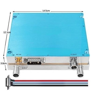
| Power Supply Interface, Monitoring Interface | RS485 7W2 Male | |
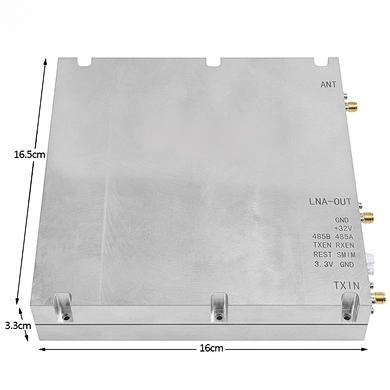
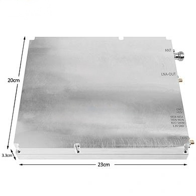
| RF Output Connector | N-F connector | |
| LCD Liquid Crystal Display | Displays frequency, power, switch status with 3 LED lights: POWER, RUN, ALARM | |
| Built-in Cooling Fan | Yes | Modules can be run separately |
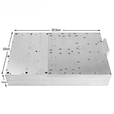
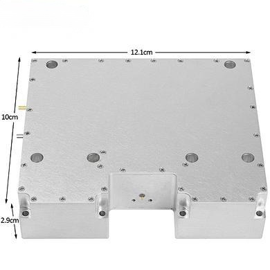
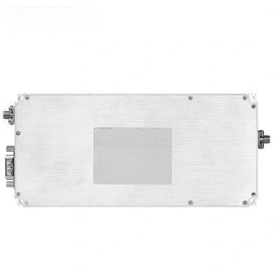
| Physical Dimensions | 255x165x80 | mm |
| Weight | 3.5 | Kg |
| Appearance (How to Use) | Black integrated module with fan (single or portable use) |
nn
Module Software Settings and Monitoring Functions
n
The module’s software offers comprehensive monitoring and alarm capabilities to ensure optimal performance and safety. Below is a detailed breakdown of the amplifier and signal generator settings.
nn
Amplifier Part: Setting Parameters
n
| Parameter | Function Description | Remarks |
|---|---|---|
| Amplifier Switch | Turn the amplifier on or off | |
| Alarm Switch | Enable and disable the alarm function | |
| Downlink Power Control | Set max output power; adjustment range ≥20dB; set high, medium, low power levels | |
| Amplifier Over Temperature Alarm | Set high temperature shutdown threshold; shuts down above 85℃, restores at 65℃ | |
| Amplifier Overpower Alarm | Actual power value is 2dB higher than downlink ALC start control threshold; closes amplifier | |
| Power Amplifier Standing Wave Alarm | Standing wave detection >4; automatically turns off amplifier | |
| Amplifier Overcurrent Alarm | Detection current exceeds 12A; automatically turns off amplifier | |
| Amplifier Under-power Alarm | Detection power less than 37dBm; displays under-power alarm | |
| Amplifier Overvoltage Alarm | Voltage exceeds 32V; automatically shuts down amplifier |
nn
Amplifier Part: Query Parameters
n
| Parameter | Function Description | Remarks |
|---|---|---|
| Amplifier Switch Status | If set to OFF, queries off state; otherwise, queries on state | |
| Downstream Output Power Level Value | Detects output power; range (Pomax+2, Pomax-20); accuracy: Pout±1dB | |
| Downward Standing Wave Ratio | Normally 1.2; when load mismatched, query value is 4.0 | |
| Temperature Query | Detects internal temperature; range: -40℃~+100℃; error: ±3℃ | |
| ALC Value Query | Displayed value equals actual set ALC value | |
| Voltage Detection | Detects module working voltage | |
| Current Detection | Detects module operating current |
nn
Signal Generator Settings
n
| Frequency Setting Mode | Function Description | Remarks |
|---|---|---|
| Mode 1 | Set any single frequency point within range | Accuracy 1M; max bandwidth 100M; max 6G |
| Mode 2 | Set broadband frequency sweep; parameters: frequency, interval, step | |
| Mode 3 | Set any 4 sub-frequency segments within bandwidth; single sub-segment needs incremental setting |
nn
Module Communication: RS485 Interface Definition
n
| Pin | Signal |
|---|---|
| + | 28V |
| – | GND |
| Control Bit 1 | 485A |
| Control Bit 2 | 485B |
nn
A New Standard in RF Performance
n
This Ultra-wideband 700-6000MHz 50W power amplifier and DDS signal generator module is not just a piece of equipment; it’s a catalyst for innovation. Its robust design, coupled with comprehensive monitoring and alarm functions, ensures you can push boundaries with confidence. From the precise frequency generation of the DDS to the reliable power amplification and thermal management, every feature is engineered for excellence. Don’t settle for less when you can unlock a new RF experience. Invest in this artifact today and elevate your projects to the next level of efficiency and stability.