Unleash Reliable Signal Power with the Ku-Band Antenna Mount Amplifier
nn
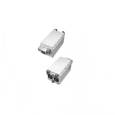
Are you grappling with unreliable signal transmission in the demanding field of satellite communications? The MOP-KU-SBU-200W Ku-band Antenna Mount Amplifier from MOP Tech is engineered to be your ultimate solution. This robust amplifier delivers a staggering traveling wave tube power of 200W, with a minimum rated power at the amplifier flange of 175W. This ensures a stable, high-power signal capable of long-distance transmission without degradation. The device operates with precision across a broad frequency spectrum, featuring an output range of 14 – 14.5 GHz and an input range of 950 – 1700 MHz, making it adaptable to various communication protocols and standards.
nn
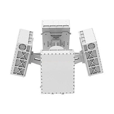
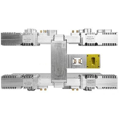
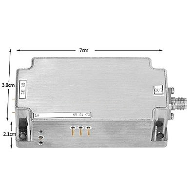
The integrated block upconverter design is a game-changer. By eliminating the need for a separate outdoor unit, it dramatically reduces installation costs and simplifies the entire setup process. This high level of internal integration—encompassing RF filters, a cooling system, and a comprehensive monitoring and control system—results in a compact form factor. This space-saving design not only minimizes footprint but also reduces signal transmission losses, enhancing overall system efficiency.
nn
Resilience in Extreme Environments
nn
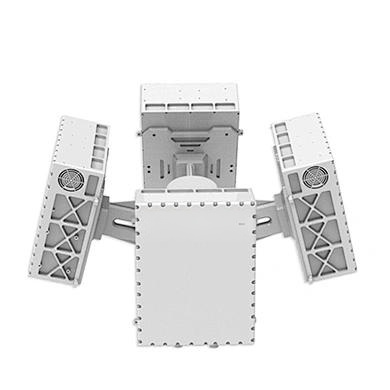
This amplifier is built to thrive where other equipment falters. With an operating temperature range from -40°C to +50°C (with a 2°C per 1000 feet derating), it performs reliably in arctic cold or scorching heat. It operates smoothly at altitudes up to 10,000 feet and withstands 100% condensing humidity without issue. Forced air cooling ensures efficient heat dissipation, maintaining optimal performance even under continuous high-power operation. This environmental ruggedness makes it ideal for remote, challenging locations.
nn
Flexible Control and Configuration Options
nn
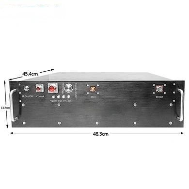
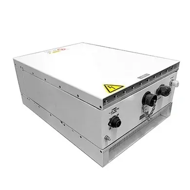
Rich interface options and a flexible configuration architecture set this amplifier apart. Remote control is fully supported through a remote external controller, allowing effortless operation from a chosen location. An Ethernet interface, complete with M&C cable and software driver, enables comprehensive PC-based management. Whether you need a single-threaded, redundant, or phase-combined configuration, the system adapts instantly to meet diverse operational demands. Don’t hesitate—elevate your communication infrastructure today.
nn
| Parameter | Specification |
|---|---|
| Frequency Range (Output) | 14 – 14.5 GHz / 13.75 – 14.5 GHz |
| Frequency Range (Input) | 950 – 1450 MHz / 950 – 1700 MHz |
| LO Frequency | 13050 MHz / 12800 MHz |
| Max Input Level (without damage) | 10 dBm |
| Reference Signal Frequency | External 10 MHz |
| Reference Signal Power Level | 2 dBm ±5 dB |
| Input Impedance | 50 Ohms |
| Output Power (Traveling Wave Tube) | 200 Watts |
| Rated Power @ Amplifier Flange (min) | 175 Watts |
| Large Signal Gain (min) | 67 dB |
| Small Signal Gain (min) | 72 dB |
| Attenuator Range (continuous) | 25 dB |
| Max SSG Variation (any 80 MHz) | 1.3 dB per 80 MHz |
| Full Band Slope (max) | ±2 dB |
| Slope (max) | ±0.04 dB/MHz |
| Stability (24 hr, max) | ±0.25 dB |
| Stability over Temperature (max) | ±1.0 dB |
| Harmonic Output (max) | -60 dBc |
| AM/PM Conversion (max) | 2.5 deg/dB at 6 dB below rated output |
| Intermodulation (max, two equal carriers) | -18 dBc @ 4 dB total output backoff |
| Noise Power (Transmit Band, max) | -70 dBW/4 kHz |
| Noise Power (Receiver Band, max) | -150 dBW/4 kHz |
| Group Delay (Linear, any 80 MHz, max) | ±0.01 nS/MHz |
| Group Delay (Parabolic, any 80 MHz, max) | ±0.005 nS/MHz² |
| Group Delay (Ripple, max) | 0.5 nS/Pk-Pk |
| Residual AM Noise (max, >100 kHz from carrier) | -60 dBc |
| Sum of All Spurs (max) | -45 dBc |
| Phase Noise (max) | 10 dB below IESS profile |
| VSWR (Input, max) | 1.6:1 |
| VSWR (Output, max) | 2.2:1 (1.3:1 with optional isolator) |
| Prime Power | 90 to 264 VAC, 47 to 63 Hz, Single Phase, 850 VA max |
| Minimum Prime Power Factor | 0.96 |
| Non-Operating Temperature Range | -50°C to +70°C |
| Operating Temperature Range | -40°C to +50°C (2°C/1000 ft derating) |
| Humidity | Up to 100% condensing |
| Altitude (max) | 10,000 feet MSL |
| Cooling | Forced Air |
| Remote Control Interfaces | HV ON/OFF, RF Inhibit, RF Attenuation, Fault, Constant Power, Heater Standby, Min/Max Power Alarm/Fault |
| Remote Status Monitoring | HV ON, Heater/Beam Hours, RF Output Power, Fault Identification, Reflected Power, TWT Temperature, Attenuator Setting, Helix Current, Filament Time Delay, Helix Voltage |
| Redundancy Interface | External Waveguide Switch Control from C, Dry Contact Closure Summary Fault |
| RF Monitor Port | -40 dB coupling (approx.) |
| Available Options | Remote External Controller, M&C Cable/Software, Input Diplexer, Reverse RF Inhibit, Internal 10 MHz, 60°C Operation, Internal Linearizer, Ethernet Connector, Extended Frequency Coverage |
nn
Mastering Signal Integrity with the Ku-Band Antenna Mount Amplifier
nn
In the world of satellite communications, signal degradation during transmission can be catastrophic. The Ku-band Antenna Mount Amplifier is designed to counteract these losses with superior performance metrics. Low intermodulation distortion (-18 dBc maximum) ensures clean signal transmission, while minimal group delay variation (0.5 nS/Pk-Pk ripple) preserves signal integrity. The amplifier’s phase noise performance sits 10 dB below the IESS profile, guaranteeing clear, reliable links even in crowded spectrum environments.
nn
Featuring a robust VSWR of 2.2:1 at the output (upgradable to 1.3:1 with an optional external isolator), the device minimizes reflections that can disrupt downstream equipment. The residual AM noise is capped at -60 dBc, further ensuring pristine signal quality. With an attenuator range of 25 dB, operators have precise control over output levels to match specific link budgets.
nn
Seamless System Integration and Monitoring
nn
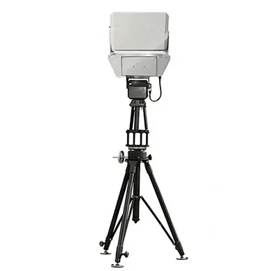
Installation is streamlined thanks to the antenna-mount design and remote control capabilities. Users can monitor critical parameters like TWT temperature, helix current, and RF output power in real-time, enabling proactive maintenance. The redundancy interface facilitates automatic switchover in failover configurations, ensuring uptime in mission-critical applications. Optional upgrades, such as an internal linearizer or extended frequency coverage, future-proof the investment.
nn
Conclusion: The Ultimate Choice for Reliable Connectivity
nn
The MOP-KU-SBU-200W Ku-band Antenna Mount Amplifier is more than just an amplifier—it’s a comprehensive solution for challenging satellite communication environments. Its powerful output, environmental resilience, flexible configurations, and precise control make it the ideal choice for broadcasters, military operators, and telecom providers. By investing in this unit, you ensure stable, high-fidelity signal transmission, reduced operational costs, and unparalleled system reliability. Choose the Ku-band Antenna Mount Amplifier today and secure your communications network for the long haul.