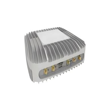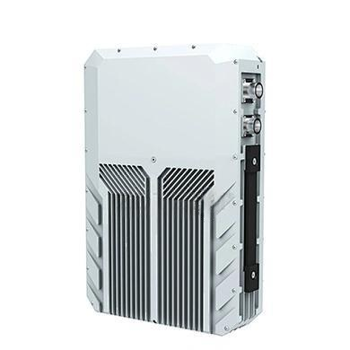
High Performance 700W Power Amplifier: Engineered for Demanding RF Applications
nn
In the world of high-power RF systems, reliability and precision are non-negotiable. Whether deployed in communication systems, test benches, or defense applications, the amplifier you choose must deliver consistent performance under harsh conditions. This article explores a robust 700W solid-state power amplifier designed to excel in the 1200-1400 MHz frequency range. We will break down its technical specifications, highlight key performance features, and examine the mechanical and environmental resilience that makes it a top-tier choice for professionals. For engineers and system integrators, understanding these parameters is essential to ensuring seamless integration and long-term operational success.
nn
Unpacking the Core Technical Specifications
nn
At its heart, this amplifier is built to provide high output power with exceptional signal clarity. The following table details the critical electrical parameters that define its performance envelope. Every value has been carefully chosen to meet or exceed industry standards for high-power amplification.
nn
| Parameter | Value | Notes |
|---|---|---|
| Operating Frequency | 1200-1400 MHz | Full L-band coverage |
| Output Peak Power (Psat) | 700 W | Saturated output |
| Gain Flatness (ATT) | ±1.5 dB | Over full bandwidth |
| Power Gain @ Psat | 58.5 dB | High gain margin |
| Input/Output VSWR | 2.5 (max) | Ensures good match |
| Spurious Signals | 60 dBc (max) | Low noise floor |
| Harmonic Rejection @ P1dB | 15 dBc (max) | Effective filtering |
| Nominal Input Power | 0 ± 3 dBm | Standard drive level |
| PA Enable/Disable Time | 2 μs | Fast switching |
| Noise Figure | 15 dB | Acceptable for power stage |
| Gain Adjustment Range | 25 dB (min) | Flexible attenuation |
| Operating Voltage | AC 220 V / 12 A | Standard mains input |
| Input/Output Impedance | 50 Ω | Industry standard |
| Input/Output Connectors | N-Type (Female) | Robust RF interface |
| Interface | RS422 | Digital control & monitoring |
nn
Understanding Key Performance Metrics
nn
The table above reveals a design philosophy centered on robustness. The 700W saturated output power enables this amplifier to drive high-gain antennas or compensate for significant cable losses. The ±1.5 dB gain flatness ensures that signals across the entire 200 MHz bandwidth receive uniform amplification, critical for modulated waveforms. Additionally, the maximum spurious output of 60 dBc means that unwanted emissions are suppressed to very low levels, protecting both the transmitter and the wider RF environment. The fast 2 μs PA enable/disable time allows for precise timing in pulsed applications, such as radar or burst-mode communications.
nn
Absolute Maximum Ratings and Environmental Durability
nn
Operating outside recommended limits can damage sensitive RF components. The following parameters define the safe operating area and the amplifier’s ability to withstand physical stress. This data is crucial for both installation planning and lifecycle cost analysis.
nn
| Parameter | Rating/Standard | Details |
|---|---|---|
| Input Overdrive | 10 dBm | Maximum safe input level |
| Operating Temperature | -30 °C to +60 °C | Wide climate range |
| Storage Temperature | -30 °C to 55 °C | Safe storage conditions |
| Relative Humidity (non-condensing) | 95% | High moisture tolerance |
| Shock/Vibration | MIL-STD-810F (Method 516.5, 514.5) | Ruggedized for mobile use |
| Vibration Test Method | MIL-STD-810D/F; Method 514.5/516.5-Proc I | Specific test protocols |
nn
Built for Extreme Conditions
nn
These ratings demonstrate that the amplifier is not a laboratory curiosity but a field-ready tool. The -30 °C to +60 °C operating range allows deployment on outdoor towers, in unheated shelters, or in desert environments. Compliance with MIL-STD-810F shock and vibration standards means it can withstand the rigors of transport, vehicle mounting, and operational shock without internal component failure. Such resilience directly translates to lower lifetime maintenance costs and higher system availability.
nn
Mechanical Design and Integration
nn
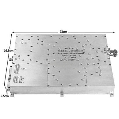
Physical form factor is as important as electrical performance when integrating into a rack or enclosure. The table below outlines the mechanical specifications that affect installation, cooling, and connectivity.
nn
| Parameter | Specification |
|---|---|
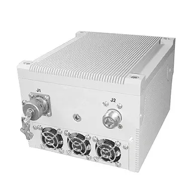
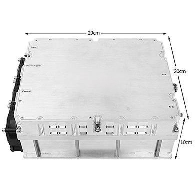
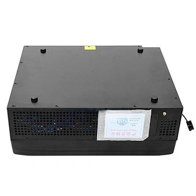
| Dimensions | 19-inch 3U standard chassis; Depth: 450 mm |
| Weight | ≤30 kg |
| RF Input/Output Connectors | N-Type (Female) |
| Power Connector | Y50DX-1203ZJ10 |
nn
Rack-Mount Simplicity
nn
The standard 19-inch 3U chassis fits directly into any conventional equipment rack, and the 450 mm depth ensures compatibility with most cabinets. The ≤30 kg weight is manageable for two-person installation. All RF connections are made via durable N-Type female connectors, and the dedicated Y50DX-1203ZJ10 power connector provides a secure, locking AC input. These details reduce integration friction and allow system designers to focus on performance, not mechanical fit.
nn
Conclusion: A Benchmark for High-Power Reliability
nn
When selecting a power amplifier for critical missions, specification sheets must translate into real-world dependability. This 700W amplifier covers the full 1200-1400 MHz band with exceptional gain flatness and low spurious output, while its rugged mechanical and environmental design guarantees operation in the harshest conditions. From the precise 58.5 dB gain to the MIL-STD shock resistance, every parameter is engineered for maximum performance. For system integrators and RF engineers, this unit represents a reliable, high-performance solution that simplifies design and ensures mission success. By examining these technical parameters in detail, you can be confident that this amplifier will meet the toughest challenges of modern RF systems.