
Understanding the High-Power Repeater Amplifier: Key Technical Parameters for Optimal Performance
nn
In the world of wireless communication, ensuring robust signal coverage is essential. Whether you’re deploying a cellular network in a challenging environment or enhancing indoor reception, the performance of your amplifier directly impacts reliability. This article dives deep into the technical parameters of a specialized amplifier designed for the 2110–2170 MHz frequency band, commonly used in 4G LTE and 5G NR systems. By exploring its specifications, we’ll uncover how each parameter contributes to efficient signal amplification, reduced interference, and long-lasting operation. Understanding these metrics helps engineers and technicians select the right hardware for their needs while ensuring compliance with industry standards.
nn
Core Technical Parameters Explained
nn
At the heart of any RF amplifier are its operational characteristics. The device in question operates at a working frequency of 2110–2170 MHz, perfectly aligning with downlink bands for mobile networks. The saturated power output reaches 40±1 dBm, which translates to approximately 10 watts. This high-power level ensures strong signal propagation, even in large buildings or outdoor installations. Coupled with a gain of 45±1 dB, the amplifier can boost weak incoming signals significantly without introducing distortion. The in-band flatness, measured at ≤±1 dB, guarantees consistent performance across the entire frequency range, preventing signal attenuation at band edges.
nn
Impedance Matching and Signal Purity
nn
For seamless integration with antennas and other RF components, the input and output VSWR (Voltage Standing Wave Ratio) must be ≤1.5. This low VSWR indicates excellent impedance matching, minimizing reflected power and maximizing energy transfer. Additionally, out-of-band spurs are tightly controlled: from 9 kHz to 1 GHz, emissions are ≤-36 dBm/30 kHz, and from 1 GHz to 12.75 GHz, they are ≤-30 dBm/30 kHz. These stringent limits ensure that the amplifier does not interfere with adjacent communication channels, making it suitable for dense urban environments with multiple wireless services.
nn
Power, Interface, and Environmental Specifications
nn
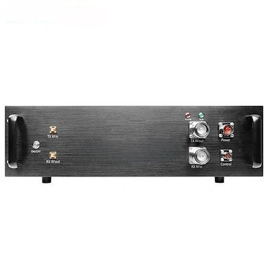
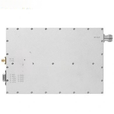
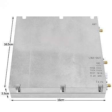
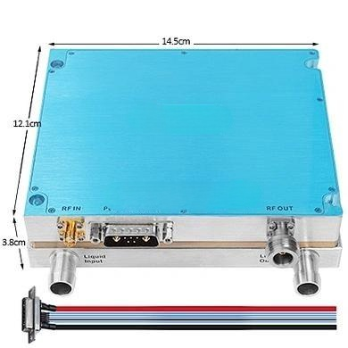
The amplifier’s design caters to practical deployment scenarios. The maximum lossless input is +10 dBm, meaning the device can handle strong input signals without clipping or compression under normal conditions. Operating voltage is a standard DC +28V, and the working current is ≤2.5A, equating to a maximum power consumption of 70 watts. This efficiency is crucial for battery-backed or solar-powered installations. The power supply interface uses a VH3.96-2PIN socket, while the RF port is an SMA-KFD connector—both industry-standard for reliable connections. For monitoring and control, an XH2.54-4PIN socket is provided, enabling real-time supervision of amplifier status.
nn
Mechanical and Environmental Resilience
nn
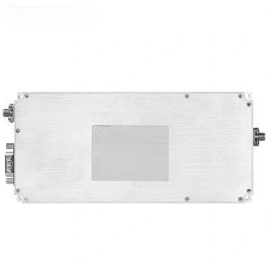
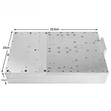
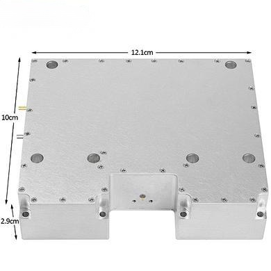
Physical dimensions of the amplifier are 135×45×19 mm, allowing for compact installation in enclosures or rack setups. The operating temperature range spans -10°C to +55°C, and relative humidity can vary from 5% to 95% without condensation, ensuring functionality in diverse climates. Storage temperature extends from -25°C to +65°C, accommodating seasonal storage or shipping conditions. These environmental tolerances highlight the unit’s suitability for both indoor and outdoor use, provided proper weatherproofing is applied.
nn
Complete Technical Parameter Table
nn
| Parameter | Specification |
|---|---|
| Working Frequency | 2110–2170 MHz |
| Saturated Power Output | 40±1 dBm |
| Gain | 45±1 dB |
| In-Band Flatness | ≤±1 dB |
| Input and Output VSWR | ≤1.5 |
| Out-of-Band Spurs (9 kHz–1 GHz) | ≤-36 dBm/30 kHz |
| Out-of-Band Spurs (1–12.75 GHz) | ≤-30 dBm/30 kHz |
| Maximum Lossless Input | +10 dBm |
| Operating Voltage | DC +28V |
| Working Current | ≤2.5A |
| Power Supply Interface | VH3.96-2PIN Socket |
| RF Port | SMA-KFD |
| Monitoring Interface | XH2.54-4PIN Socket |
| Amplifier Size | 135 × 45 × 19 mm |
| Operating Temperature | -10°C to +55°C |
| Relative Humidity | 5%–95%, No Condensation |
| Storage Temperature | -25°C to +65°C |
nn
Conclusion: Leveraging Technical Parameters for Reliable Communication
nn
The comprehensive set of technical parameters presented here underscores the amplifier’s role as a high-performance building block for modern wireless systems. From its precise frequency range and power output to robust impedance matching and environmental endurance, every specification is engineered to minimize signal loss and interference. By carefully evaluating these parameters—such as gain flatness, VSWR, and spurious emissions—network designers can ensure that the amplifier not only meets coverage requirements but also coexists harmoniously with other RF equipment. Whether deployed in a 4G small cell or a private 5G network, this device demonstrates how meticulous attention to technical details translates into reliable, efficient signal amplification. As wireless demands continue to grow, understanding and applying these technical parameters will remain essential for optimizing communication infrastructure worldwide.