Understanding the RF Booster: Technical Specifications and Performance Metrics
nn
When selecting a high-performance RF booster for your telecommunications infrastructure, it is essential to understand the detailed specifications that define its capabilities. This article provides a comprehensive breakdown of the core parameters, ensuring you can make an informed decision for your network needs. From frequency ranges to power output and signal integrity, each factor plays a critical role in achieving optimal coverage and reliability. By examining the RF booster specification table below, you will gain clarity on how this device operates across different bands and conditions, helping you match it to your specific application requirements.
nn
The primary function of this RF booster is to amplify weak signals while maintaining strict adherence to frequency allocations and regulatory standards. Whether you are enhancing UMTS900, LTE FDD1800, or UMTS2100 bands, the device is engineered to deliver exceptional gain and linearity. Let us explore the detailed technical parameters that make this equipment a robust solution for modern wireless communication systems.
nn
Frequency and Bandwidth Overview
nn
The RF booster specification covers three distinct frequency bands, each with specific uplink and downlink ranges. The UMTS900 band operates between 880-915 MHz for uplink and 925-960 MHz for downlink, providing a bandwidth of 5 MHz across four sub-bands. For LTE FDD1800, the uplink spans 1710-1785 MHz with a downlink of 1805-1880 MHz, offering a much wider 60 MHz bandwidth in a single sub-band. The UMTS2100 band covers 1920-1980 MHz uplink and 2110-2170 MHz downlink, with 10 MHz bandwidth distributed across four sub-bands. This multi-band capability ensures compatibility with various network technologies, making the booster versatile for operators transitioning between 3G and 4G systems.
nn
Power Output and Gain Characteristics
nn
Maximum total output power is rated at 27±2 dBm for UMTS900 and UMTS2100, while LTE FDD1800 achieves 40±2 dBm at the center frequency. The gain at center frequency and 25°C is specified as 90±3 dB for UMTS900/UMTS2100 and 95±3 dB for LTE FDD1800. These values indicate the booster’s ability to significantly enhance signal strength while maintaining precision. The adjustable attenuation range spans from 0 to 30 dB in 1 dB steps, with an error tolerance of ≤ |±1.5| dB, allowing fine-tuned control over output levels. Additionally, the Automatic Level Control (ALC) operates within 0-25 dB to prevent over-amplification and protect connected equipment.
nn
Signal Quality and Noise Performance
nn
To preserve signal clarity, the noise figure at maximum gain is ≤ 10.0 dB, ensuring minimal degradation of the original signal. The input Voltage Standing Wave Ratio (VSWR) under powered-up conditions, minimum gain, and -30 dBm input is ≤ 2.0, indicating good impedance matching. Ripple in band (peak-to-peak) at +25°C is tightly controlled: for UMTS900, it is ≤ ±4.5 dB within the essential bandwidth (882-913 MHz uplink / 927-958 MHz downlink) and ≤ ±6.5 dB across the full band (880-915 MHz / 925-960 MHz). Similar precision applies to LTE FDD1800 and UMTS2100, ensuring flat frequency response across the operational range.
nn
Comprehensive RF Booster Specification Table
nn
| Parameter | UMTS900 Band | LTE FDD1800 Band | UMTS2100 Band |
|---|---|---|---|
| Uplink Frequency Range (MHz) | 880 ~ 915 | 1710 ~ 1785 | 1920 ~ 1980 |
| Downlink Frequency Range (MHz) | 925 ~ 960 | 1805 ~ 1880 | 2110 ~ 2170 |
| Bandwidth (MHz) | 5M | 60M | 10M |
| Sub-band Number | 4 | 1 | 4 |
| Max. Total Output Power (dBm) at Center Frequency | 27±2 | 40±2 | 27±2 |
| Max. Gain (dB) at Center Frequency, 25°C | 90±3 | 95±3 | 90±3 |
| ATT Adjustable Range (dB) / (Step) | 0~30 @ 1 dB step | ||
| ATT Adjustable Error (dB) | ≤ |±1.5| | ||
| ALC (dB) | 0~25 | ||
| Noise Figure (dB) at Max. Gain | ≤ 10.0 | ||
| Input VSWR (Power up, Min Gain, Pin=-30dBm) | ≤ 2.0 | ||
| Ripple In Band (P-P) (dB) at +25°C | 882-913M/927-958M: ≤±4.5@EBW; 880-915M/925-960M: ≤±6.5@EBW | 1712-1783M/1807-1878M: ≤±4.5@EBW; 1710-1785M/1805-1880M: ≤±6.5@EBW | 1922-1978M/2112-2168M: ≤±4.5@EBW; 1920-1980M/2110-2170M: ≤±5.5@EBW |
| Out of Band Gain at 25°C (dB) | 2.7≤f_offset<3.5MHz: ≤80; 3.5≤f_offset<7.5MHz: ≤60; 7.5≤f_offset<12.5MHz: ≤45; 12.5MHz≤f_offset: ≤35 | ||
| Out of Band Rejection (dBc) at +25°C for LTE1800 | ±5MHz offset: ≤-15; ±8MHz offset: ≤-30; ±12MHz offset: ≤-45 | ||
| Spurious Emission (dBm) at 10MHz Offset | 9kHz~150kHz: ≤ -36dBm/1KHz; 150kHz~30MHz: ≤ -36dBm/10KHz; 30MHz~1GHz: ≤ -15dBm/100KHz; 1GHz~12.75GHz: ≤ -10dBm/1MHz | ||
| EVM (%) for UMTS | ≤ 12.5 | ≤ 12.5 | |
| PCDE (dB) for UMTS | ≤ -35 | ≤ -35 | |
| EVM (%) for LTE | N/A | ≤ 8.0 | N/A |
| Time Delay (us) | ≤ 7.0 | ||
| RF Connector | N(f) | ||
| Input/Output Impedance (Ω) | 50 | ||
| Power Supply | AC176-264V | ||
| Temperature Range (°C) | -25 ~ +55 | ||
| Humidity Range (%) | 5~95 | ||
| Weight (Kg) | ≤35 | ||
| Dimension (mm) | 489409186.5 | ||
| Installation | Wall Mounting | ||
| Device Cooling | Cooling with fan | ||
| Monitor & Alarm | Local Monitor: RJ45; Remote Monitor: SMS (4G Modem) | ||
nn
Environmental and Operational Considerations
nn
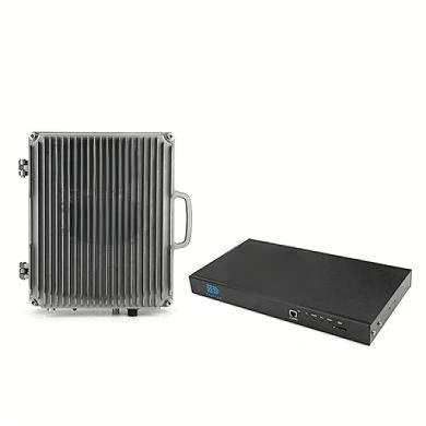
The RF booster specification also includes key environmental and installation parameters. The device operates within a temperature range of -25°C to +55°C and humidity from 5% to 95%, making it suitable for both indoor and sheltered outdoor deployments. Weighing ≤ 35 kg and measuring 489 x 409 x 186.5 mm, it is designed for wall mounting, with active fan cooling to manage heat dissipation. Monitoring is facilitated through a local RJ45 port and remote SMS alerts via a 4G modem, enabling real-time supervision and fault detection. These features ensure that the booster maintains consistent performance under varying conditions, from harsh weather to fluctuating power supply demands.
nn
Conclusion: Why This RF Booster Specification Matters
nn
In conclusion, the detailed RF booster specification presented here provides a complete picture of the device’s capabilities, from frequency agility and high gain to rigorous signal quality standards. Whether you are deploying it for UMTS or LTE networks, the booster delivers dependable amplification with precise control over attenuation, ripple, and spurious emissions. The robust design, combined with comprehensive monitoring options, makes it a reliable choice for critical communication infrastructure. By understanding these specifications, you can ensure that your network expansion or upgrade project achieves the desired coverage, capacity, and performance levels. For any application requiring consistent signal enhancement, this booster stands as a technically sound investment, backed by transparent and thorough performance metrics.