Introduction: Understanding the DCS1800 and WCDMA2100 Repeater Key Specifications
n
When deploying a mobile signal repeater for DCS1800 and WCDMA2100 bands, the technical specifications determine network performance, coverage quality, and device compatibility. This article decodes the critical parameters, explaining how each specification impacts real-world signal boosting. Whether you are an installer or a network engineer, grasping these details ensures optimal system setup and troubleshooting.
nn
Frequency and Power Specifications
n
Operating Bands and Frequency Ranges
n
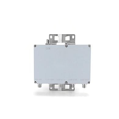
The repeater supports two primary bands. The uplink and downlink frequencies are distinct, ensuring efficient communication between the base station and mobile devices. The DCS1800 band uses 1710–1785 MHz for uplink and 1805–1880 MHz for downlink. For WCDMA2100, the uplink spans 1920–1980 MHz, while the downlink covers 2110–2170 MHz. This dual-band capability allows seamless operation across 2G, 3G, and some 4G networks.
nn
Maximum Output Power and Gain
n
Output power is a key metric. For uplink, the maximum output power is -10±2 dBm, while the downlink delivers 43±2 dBm at maximum gain and center frequency. Gain levels reach 55±3 dB for both paths when optical loss is zero. This high gain ensures weak signals are amplified effectively, extending coverage in challenging environments.
nn
| Parameter | Uplink | Downlink |
|---|---|---|
| Frequency Range (MHz) DCS1800 Band | 1710 ~ 1785 | 1805 ~ 1880 |
| Frequency Range (MHz) WCDMA2100 Band | 1920 ~ 1980 | 2110 ~ 2170 |
| Max. Output Power (dBm) (Max. Gain, Center Frequency) | -10±2 | 43±2 |
| Max. Gain (dB) (Center Frequency) @Optical Loss=0dB | 55±3 | 55±3 |
| ATT Adjustable Range (dB) | 0 ~ 30 | 0 ~ 30 |
| ATT Adjustable Step (dB) | 1 | 1 |
| ATT Adjustable Error (dB) | ≤ |±1.5| | ≤ |±1.5| |
| ALC Range (dB) | 0 ~ 20 | 0 ~ 20 |
| ALC Accuracy (dB) | ≤ |±2.0| | ≤ |±2.0| |
| Frequency Error (ppm) | ≤± 0.05 | ≤± 0.05 |
| Ripple In Band (dB) at 25℃ DCS1800 Band | ≤ 7.0 | ≤ 7.0 |
| Ripple In Band (dB) at 25℃ WCDMA2100 Band | ≤ 6.0 | ≤ 6.0 |
| 3rd Inter-modulation attenuation (dBc) (Max. Gain, Dual tone interval of 600KHz) | ≤ -40 | ≤ -40 |
| EVM (%) @WCDMA2100 | ≤12.5 | ≤12.5 |
| PCDE (dB) @WCDMA2100 | ≤-35 | ≤-35 |
| Out of band Spurious Emission (dBm) at offset ±10MHz 9kHz~150kHz | ≤ -36/1KHz | ≤ -36/1KHz |
| Out of band Spurious Emission (dBm) at offset ±10MHz 150kHz~30MHz | ≤ -36/10KHz | ≤ -36/10KHz |
| Out of band Spurious Emission (dBm) at offset ±10MHz 30MHz~1GHz | ≤ -36@100KHz | ≤ -36@100KHz |
| Out of band Spurious Emission (dBm) at offset ±10MHz 1GHz~12.75GHz | ≤ -5@1MHz | ≤ -5@1MHz |
| Time Delay (us) | ≤5 | ≤5 |
| VSWR (Power up, Min Gain, Pin=-30dBm) DCS1800 Band | ≤ 1.8 | ≤ 1.8 |
| VSWR (Power up, Min Gain, Pin=-30dBm) UMTS2100 Band | ≤ 1.8 | ≤ 1.8 |
| Noise Figure (dB) (Max. Gain) | ≤ 7.0 | / |
| Absolute Maximum Input RF Power (1 min) | UL:≤-10dBm | DL:≤10dBm |
nn
Signal Quality and Distortion Metrics
n
Ripple, Inter-modulation, and Modulation Accuracy
n
In-band ripple at 25°C is kept under 7.0 dB for DCS1800 and 6.0 dB for WCDMA2100, ensuring signal flatness across the spectrum. Third-order inter-modulation attenuation is ≤ -40 dBc, minimizing interference from adjacent channels. For WCDMA2100, Error Vector Magnitude (EVM) stays ≤12.5%, and Peak Code Domain Error (PCDE) is ≤ -35 dB, preserving signal integrity for voice and data transmission.
nn
Spurious Emissions and Frequency Stability
n
Out-of-band spurious emissions are tightly controlled. From 9 kHz to 150 kHz, the limit is -36 dBm/1kHz; from 150 kHz to 30 MHz, -36 dBm/10kHz; from 30 MHz to 1 GHz, -36 dBm/100kHz; and from 1 GHz to 12.75 GHz, -5 dBm/1MHz. Frequency error is limited to ±0.05 ppm, ensuring precise carrier tracking. These values prevent interference with other wireless services.
nn
Reliability and Installation Parameters
n
Time Delay, VSWR, and Noise Figure
n
Time delay is ≤5 microseconds, critical for maintaining synchronous communications. Voltage Standing Wave Ratio (VSWR) for both bands is ≤1.8 at minimum gain with -30 dBm input, indicating good impedance matching. Noise figure is ≤7.0 dB at maximum gain, keeping the system from degrading the signal-to-noise ratio. The absolute maximum input RF power for uplink is -10 dBm and for downlink is 10 dBm, protecting the unit from overload.
nn
Conclusion: Mastering Repeater Specifications for Optimal Performance
n
Understanding these repeater specifications empowers you to select and configure the right system for your network. From frequency ranges and power output to distortion metrics and installation parameters, each specification plays a vital role. The DCS1800 and WCDMA2100 bands are covered comprehensively, ensuring reliable signal amplification. By focusing on these key DCS1800 and WCDMA2100 specifications, you can achieve seamless connectivity and extended coverage in any environment. Always refer to the technical data sheet for precise values during installation, and use the table above as a quick reference for system tuning and troubleshooting. This approach guarantees that your repeater operates at peak efficiency, delivering the performance you expect.