Unlocking Network Performance: Understanding the Technical Parameters of a 700-960 MHz Repeater Amplifier
nnIn the world of wireless communications, the efficiency and reliability of signal amplification are paramount. Whether you are addressing rural coverage gaps or enhancing in-building connectivity, the heart of the system lies in the amplifier’s technical specifications. A deep dive into the technical parameters of a 700-960 MHz repeater amplifier reveals how each specification, from frequency band to power supply, dictates real-world performance.nn
Frequency Band and Power: The Core of the Technical Parameters
nThe foundation of any amplification system is its ability to operate within the correct spectrum. This unit covers a critical frequency band of 700-960 MHz, a range widely used for LTE and 5G low-band networks. The max output power, listed at ≥53 dBm, is exceptionally high, translating to roughly 200 watts. This power level is not merely a number; it defines the cell radius. Combined with a max gain of 53±1.5 dB (which is customizable), these technical parameters ensure that weak uplink and downlink signals are boosted to a level capable of penetrating obstacles and covering significant distances.nn
Signal Integrity and Purity: Fluctuation and Spurious Emissions
nPower is useless without clarity. The in-band fluctuation (peak-to-peak) is specified at ≤1.5 dB. This tight control is crucial. Excessive fluctuation would distort the modulated signal, leading to dropped calls or data retransmissions. Furthermore, the amplifier must not pollute the airwaves. Spurious emissions are strictly limited: -36 dBm from 9kHz to 1GHz, and -30 dBm from 1GHz to 12.75GHz. These levels are not arbitrary; they comply with stringent regulatory standards (FCC/ETSI), ensuring the device does not interfere with adjacent channels or other critical services like aviation or emergency radios.nn
Impedance Matching and Protection: The VSWR and Safety Specifications
nMaintaining a low Voltage Standing Wave Ratio (VSWR) of ≤1.6 is a critical technical parameter. VSWR measures how efficiently power is transmitted from the amplifier to the antenna. A high VSWR indicates power is being reflected back into the amplifier, potentially causing damage and reducing efficiency. This device integrates multiple layers of intelligent protection:n
- n
- Open Circuit Protection: If the VSWR exceeds 2.5 dB, the PA switches off immediately. The indicator light activates, and the system restarts automatically to recover.
- Overheating Protection: The unit will automatically shut down at ≥90°C and resume normal operation once the temperature drops to ≤65°C.
- Output Open Circuit Alarm: An M2.5 feedthrough capacitor provides a high-level alarm if the output is disconnected.
n
n
n
nThese safeguards ensure longevity and protect the expensive power amplifier transistors.nn
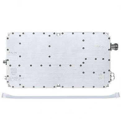
Power Supply and Environmental Technical Parameters
nHigh power requires robust support. The supply voltage is 32V, and the working current is ≤20A at full power. This indicates a high-efficiency design. The operational temperature range of -40 to +55℃ ensures functionality in extreme climates, from arctic installations to desert base stations. The power supply interface uses an M4.0 feedthrough capacitor, a design choice that minimizes RF leakage and improves electromagnetic compatibility.nn
| Parameter | Value | Remarks |
|---|---|---|
| Frequency Band (MHz) | 700-960 | LTE/5G Low Band |
| Max. Output Power (dBm) | ≥53 | ~200 Watts |
| Max. Gain (dB) | 53±1.5 | Customizable |
| In-Band Fluctuation (p-p) (dB) | ≤1.5 | Signal Fidelity |
| Spurious Emissions | 9kHz-1GHz: ≤-36dBm | RBW=100kHz |
| Spurious Emissions (cont.) | 1GHz-12.75GHz: ≤-30dBm | RBW=1MHz |
| VSWR | ≤1.6 | Reflection Loss |
| Supply Voltage (V) | 32 | DC |
| Working Current (A) | ≤20 | @Full Power |
| Working Temperature (℃) | -40 to +55 | Industrial Grade |
| Power Supply Interface | M4.0 Feedthrough | EMC Protection |
| RF Port ANT IN | SMA | Input |
| RF Port ANT OUT | N-type | Output (Customizable) |
| Switch Control | M2.5 Feedthrough | High=On, Low=Off (Vhigh=2.5V) |
| Output Open Circuit Alarm | M2.5 Feedthrough | High Level Alarm |
| Communication Monitoring | 14Pin 2.5 Pitch | Pin1:A; Pin2:GND; Pin3:B; Pin4:NC |
| Temperature Detection Error | ≤3℃ | Accuracy |
| Downlink Output Power Detection | ≥20dB | (P0+2 – P0-18) |
| Open Circuit Protection | VSWR > 2.5 | Auto Restart/Recovery |
| Overheating Protection | 90℃ On / 65℃ Off | Automatic |
| Embedded Software Environment | RS485 Full Connectivity | Monitor Temp, Outflow, Downlink Control |
| Material | Aluminum | Lightweight/Durable |
| Size (mm) | L220W118H27 | Reference |
| Installation Hole Spacing | M4 | Fixed Pattern |
nn
Intelligent Control: Embedded Software and Monitoring
nModern amplifiers are smart nodes. The embedded software environment is fully connected to RS485. This allows remote management of crucial functions: controlling actual temperature, monitoring outflow rate (power), and adjusting downlink decline control. This telemetry ensures the network operator can fine-tune the amplifier’s performance without physical access.nn
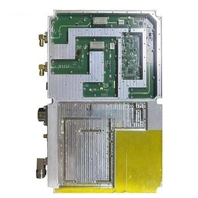
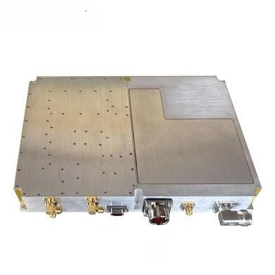
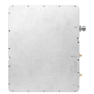
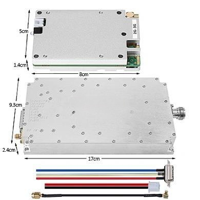
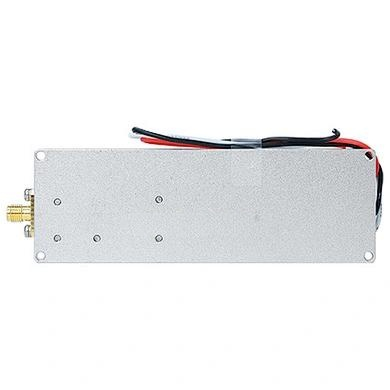
Physical Design and Integration Technical Parameters
nThe physical footprint is compact at L220W118*H27 mm, constructed from aluminum for thermal dissipation. The RF port configuration offers flexibility: the ANT IN port uses an SMA connector for the donor antenna, while the ANT OUT uses an N-type connector (customizable to other types). The fixed M4 hole spacing simplifies mounting on brackets or walls.nn
Conclusion: Why These Technical Parameters Matter for Network Success
nIn summary, the technical parameters of this repeater amplifier are not a random list of numbers but an integrated system designed for reliability, power, and control. From the stringent spurious emission limits ensuring regulatory compliance to the intelligent VSWR and overheating protection guaranteeing operational safety, every detail serves a purpose. Mastering these technical parameters allows engineers to deploy a solution that maximizes coverage while minimizing interference, making it an indispensable tool for modern wireless infrastructure. The robust build and smart monitoring capabilities ensure that this amplifier will perform under the harshest conditions, delivering the signal strength needed for seamless connectivity.