Introducing the MOP-LPDA-727/740 Series: Versatile Log-Periodic Dipole Array Antennas
nnWhen it comes to reliable wireless communication, the antenna you choose can make or break your system’s performance. The MOP-LPDA series from MOP® is designed to deliver exceptional signal clarity and robust connectivity across multiple frequency bands. Whether you need to cover sub-1 GHz cellular, LTE, 5G, or even higher-frequency Wi-Fi and IoT applications, these log-periodic dipole arrays are engineered to meet your most demanding specifications. This article explores the critical electrical and mechanical characteristics of the MOP-LPDA-727 and MOP-LPDA-740 models, showing why they are trusted by RF engineers and system integrators worldwide.nn
Understanding the Electrical Specifications of MOP-LPDA Series Antennas
nnAntenna selection starts with understanding the core electrical parameters. The MOP-LPDA-727 and MOP-LPDA-740 models share a common design philosophy—low VSWR, high gain, and excellent passive intermodulation (PIM) performance—yet they differ in their frequency coverage and beamwidth profiles. Below is a comprehensive table detailing the electrical specifications for both models across their standard and extended frequency variants.nn
| Parameter | MOP-LPDA-727-X/XNF (MF/SF) | MOP-LPDA-740-X/XNF (MF/SF) |
|---|---|---|
| Frequency Range (MHz) | 698–960 / 1710–2700 | 690–960 / 1710–2700 / 3400–4000 |
| Gain (dBi) | 8±1 (698–960) / 9±1 (1710–2700) | 8±1 (690–960) / 8.5±1 (1710–2700) / 9±1 (3400–4000) 9±1 (690–960) / 10±1 (1710–2700) / 9±1 (3400–4000) 9.5±1 (690–960) / 10±1 (1710–2700) / 11±1 (3400–4000) |
| Polarization | Vertical | Vertical |
| Horizontal Beamwidth (deg) | 85±20 (698–960) / 65±15 (1710–2700) | 60±15 (690–960) / 60±15 (1710–2700) / 55±15 (3400–4000) 55±15 (690–960) / 55±15 (1710–2700) / 55±15 (3400–4000) |
| Vertical Beamwidth (deg) | 60±15 (698–960) / 55±15 (1710–2700) | 55±15 (690–960) / 55±15 (1710–2700) / 55±15 (3400–4000) |
| VSWR | ≤1.8 | ≤1.8 |
| PIM (3rd Order, 2 x 20 W, dBc) | -153 | -153 |
| Input Power (maximum, watt) | 50 | 50 |
| Impedance (ohm) | 50 | 50 |
nnThe gain values shown in the table highlight the versatility of the MOP-LPDA series. For instance, the MOP-LPDA-740 offers multiple gain options across its three frequency bands, allowing you to balance coverage area with signal strength. Notably, the PIM performance of -153 dBc ensures low intermodulation distortion, critical for multi-carrier systems and high-traffic environments. These electrical specifications demonstrate why the MOP-LPDA-727 and MOP-LPDA-740 are ideal for indoor and outdoor distributed antenna systems (DAS), base station coverage, and point-to-point links.nn
Mechanical Specifications: Built for Durability and Easy Installation
nnBeyond electrical performance, the physical design of an antenna matters for longevity and ease of deployment. The MOP-LPDA series comes in multiple size variants to suit different mounting scenarios. The mechanical parameters are summarized below.nn
| Parameter | Value |
|---|---|
| Dimensions (H x W x D) mm | 290 x 200 x 50 / 400 x 200 x 50 / 510 x 200 x 50 |
| Weight (without mounting kit) kg | 0.51 |
| Radome Material and Color | ABS, White, RAL9003 |
| Mounting Kit | On-wall |
| Connector Type and Location | N / Din / 4.3-10 Female |
| Operational Temperature (°C) | -55 to +60 |
| Mounting Hardware (mm) | 35–50 |
nn
Design and Installation Considerations
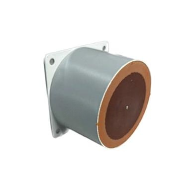
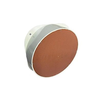
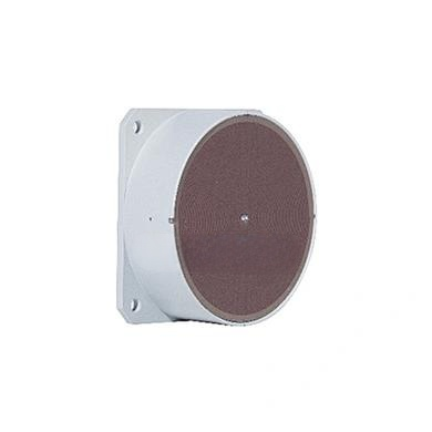
nnThe MOP-LPDA series antennas are housed in a durable ABS radome, painted white (RAL9003) to blend seamlessly with most indoor and outdoor environments. With dimensions ranging from a compact 290 mm to a larger 510 mm profile, you can choose the size that best fits your space constraints. The lightweight design (just 0.51 kg without mounting kit) simplifies handling and reduces structural load. The on-wall mounting kit supports pole or wall attachment, while the connector options (N-type, Din, or 4.3-10 female) provide flexibility for integrating with existing cabling. The operating temperature range of -55°C to +60°C ensures reliable performance in extreme climates, from arctic cold to desert heat.nn
Why the MOP-LPDA Series Excels in Modern Wireless Networks
nnThe electrical specifications of the MOP-LPDA-727 and MOP-LPDA-740 reveal a thoughtful design that prioritizes low loss and high efficiency. The VSWR of ≤1.8 across all bands means minimal reflected power, translating to better signal strength and coverage. The vertical polarization matches most cellular and Wi-Fi infrastructure, and the symmetrical beamwidth values (e.g., 55° in both planes for many variants) enable predictable pattern shaping. Additionally, the 50-ohm impedance ensures seamless compatibility with standard RF components like cables, amplifiers, and splitters.nn
Conclusion
nnWhether you’re deploying a small cell, covering a warehouse, or building a robust 5G backhaul, the MOP-LPDA-727 and MOP-LPDA-740 antennas offer a proven balance of performance and practicality. Their electrical specifications—including wide frequency coverage, high gain, and low PIM—make them suitable for mission-critical applications. Combined with a rugged mechanical design and straightforward installation, they stand out as top choices for engineers seeking reliable log-periodic dipole arrays. By investing in these antennas, you ensure your network maintains the highest standards of signal integrity and durability.