Mastering Signal Integrity: A Deep Dive into Electrical Specifications
In the demanding world of telecommunications, the performance of your network hinges on the reliability of its foundational hardware. Whether you are deploying a 5G overlay or optimizing a 4G LTE infrastructure, understanding the core electrical specifications of your components is non-negotiable. This article serves as your definitive guide, dissecting the critical parameters that define a high-performance combiner or filter module. From stringent isolation requirements to power handling capabilities, we will explore the technical nuances that ensure your network operates with zero interference, maximum efficiency, and uncompromising quality.
Understanding Frequency Band Allocation and Port Mapping
A modern combiner must seamlessly integrate multiple frequency bands without cross-contamination. The electrical specifications detail precise frequency ranges for each port, ensuring that signals are routed correctly for DCS 1800 and UMTS 2100 networks. The port mapping is meticulously organized to prevent overlap and minimize internal noise, which is vital for maintaining signal purity in dense urban environments.
Core Electrical Specifications and Performance Metrics
The heart of any RF component lies in its ability to manage signal loss, reject unwanted frequencies, and handle power without degradation. The following table outlines the rigorous electrical specifications that guarantee system reliability.
| Parameter | Band / Port | Value / Specification |
|---|---|---|
| Input Port Frequency (MHz) | DCS 1800 – Port 1 | 1710-1730 / 1805-1825 |
| DCS 1800 – Port 2 | 1730-1750 / 1825-1845 | |
| DCS 1800 – Port 3 | 1750-1770 / 1845-1865 | |
| UMTS 2100 – Port 1 | 1920-1935 / 2110-2125 | |
| UMTS 2100 – Port 2 | 1935-1965 / 2125-2155 | |
| UMTS 2100 – Port 3 | 1965-1980 / 2155-2170 | |
| Insertion Loss | All Ports | ≤ 5.5 dB |
| Isolation (Between Bands) | All Ports | ≥ 35 dB |
| Isolation (Cross Bands) | All Ports | ≥ 80 dB |
| Input Port Return Loss | All Ports | ≥ 18 dB |
| Power Handling | All Ports | 100 W |
| Intermodulation Products | All Ports | ≤ -150 dBc @ 2×43 dBm |
| Impedance | All Ports | 50 Ω |
| VSWR | All Ports | ≤ 1.3 |
Why Isolation and Intermodulation Matter
High isolation values, particularly the cross-band isolation of ≥80 dB, are critical for preventing signals from leaking between the DCS and UMTS paths. Simultaneously, the exceptionally low intermodulation distortion (≤ -150 dBc) ensures that even under high-power conditions, the combiner does not generate spurious signals that could degrade network throughput. These electrical specifications are the reason why this module can operate in high-density, multi-operator environments without interference.
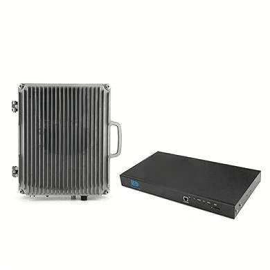
Mechanical and Environmental Resilience
Robust electrical specifications must be paired with a design that can withstand physical and climatic stress. While the unit is classified for indoor environmental class, its mechanical profile is engineered for standard infrastructure integration.
Structural Design and Integration
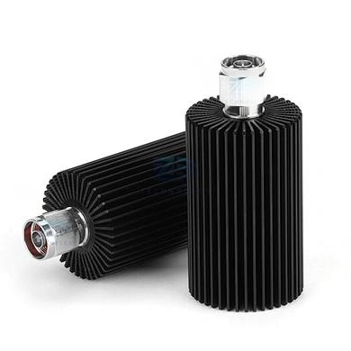
The mechanical design emphasizes compactness and standard rack mounting. The dimensions and weight remain pending final engineering validation (TBD), but the unit is designed to occupy minimal space within a 19-inch rack framework. The choice of 8 × N-Type Female connectors provides a reliable, corrosion-resistant interface for high-frequency cabling.
| Mechanical & Environmental Parameter | Specification |
|---|---|
| Dimensions (L×W×H) | TBD (excluding connectors & mounting bracket) |
| Weight | TBD |
| Shipping Dimensions | TBD |
| Shipping Weight | TBD |
| RF Connectors (Input & Output) | 8 × N – Female |
| Mounting | 19-inch Rack |
| Operating Temperature Range | -10 to +60 °C |
| Operational Humidity | ≤ 95% |
| Environmental Class | Indoor |
Conclusion: The Benchmark for System Reliability
The comprehensive electrical specifications detailed in this guide—from the precise frequency splitting to the rigorous isolation and power handling—are the cornerstone of a high-performing network. By ensuring that every parameter meets or exceeds these benchmarks, engineers can deploy infrastructure that delivers clean, strong, and reliable signals across multi-band scenarios. As the network evolves, these specifications provide the assurance needed to maintain service quality and user satisfaction. Always verify these electrical specifications against your specific deployment requirements to ensure optimal performance in your unique environment.