Unlocking RF Performance: The 0.5-6GHz Power Splitter Advantage
nnIn the demanding world of radio frequency engineering, precision and reliability are non-negotiable. Whether you are designing a 5G infrastructure, a military communication system, or a sophisticated test bench, the integrity of your signal path determines the success of your entire project. The 0.5-6GHz Power Splitter stands as a critical component, bridging the gap between signal sources and multiple outputs without sacrificing fidelity. This article explores the key specifications, design nuances, and practical applications of this versatile device, ensuring you make an informed decision for your next RF deployment.nn
Critical Performance Metrics of the 0.5-6GHz Power Splitter
nnUnderstanding the technical specifications is paramount when integrating a power splitter into your system. The device operates across a wide frequency range from 0.5 to 6 GHz, covering popular communication bands including cellular, Wi-Fi, and ISM frequencies. Its primary function is to divide an input signal into multiple outputs with minimal degradation. Below are the critical performance parameters that define its utility.nn
Insertion Loss and VSWR: The Gatekeepers of Signal Integrity
nnOne of the most vital characteristics of any power divider is its insertion loss (IL). This specification includes the inherent split loss (typically 3 dB for a 2-way splitter) plus any additional circuit losses. For this unit, the total insertion loss is ≤4.5 dB across the entire band. This low loss ensures that the signal remains strong and usable at each output port.nnEqually important are the Voltage Standing Wave Ratio (VSWR) values at both the input and output ports. A low VSWR indicates excellent impedance matching, which minimizes signal reflections and power loss. This device offers outstanding matching:n- Input VSWR: ≤1.4 from 0.5-0.6 GHz and ≤1.3 from 0.6-6 GHz.n- Output VSWR: ≤1.3 across the entire 0.5-6 GHz range.nnThese figures indicate a highly stable performance, preventing unwanted signal bounce-back that can damage sensitive transmitter components.nn
Isolation and Power Handling: Ensuring Channel Purity
nnIsolation measures how well the splitter prevents signals from one output port from leaking into another. High isolation is critical for maintaining signal quality in multi-channel systems. The 0.5-6GHz Power Splitter provides:n- Isolation: 16 dB minimum (0.5-0.6 GHz) and 20 dB minimum (0.6-6 GHz).nnThis ensures minimal crosstalk and interference between output channels. Power handling capability is a robust 50 Watts, making it suitable for moderate-power applications in test labs and small-scale base stations. The impedance is a standard 50 ohms, ensuring compatibility with almost all common RF systems, antennas, and cables.nn
Technical Specifications at a Glance
nnFor clarity and quick reference, all critical mechanical and electrical parameters are detailed in the table below.nn| Parameter | Condition / Frequency Range | Specification |n| :— | :— | :— |n| Frequency Range | Full Band | 0.5 – 6 GHz |n| Insertion Loss (incl. split loss) | 0.5 – 6 GHz | ≤ 4.5 dB |n| Isolation | 0.5 – 0.6 GHz | 16 dB min |n| | 0.6 – 6 GHz | 20 dB min |n| Input VSWR | 0.5 – 0.6 GHz | ≤ 1.4 |n| | 0.6 – 6 GHz | ≤ 1.3 |n| Output VSWR | 0.5 – 0.6 GHz | ≤ 1.3 |n| | 0.6 – 6 GHz | ≤ 1.3 |n| Power Handling | All ports | 50 Watts |n| Impedance | All ports | 50 ohms |n| Connector Type | All ports | SMA-female |n| Color | Enclosure | Silvery White |n| Operating Temperature | Environment | -45°C to +85°C |nn
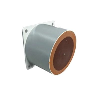
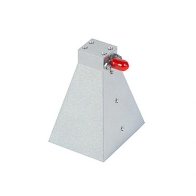
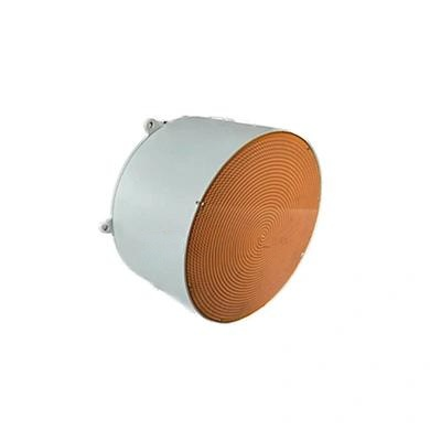
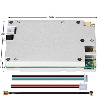
Design and Construction: Built for the Environment
nnThe physical design of the 0.5-6GHz Power Splitter is as important as its electrical characteristics. Housed in a robust silvery white enclosure, the device is engineered for durability. The use of SMA-female connectors ensures a secure, low-loss connection that is standard across the industry. This connector type is prized for its excellent performance up to microwave frequencies and its ability to withstand repeated mating cycles.nnFurthermore, the wide operating temperature range of -45°C to +85°C allows deployment in both indoor labs and harsh outdoor environments, from unventilated equipment shelters to extreme climate conditions. This thermal resilience guarantees consistent electrical performance regardless of ambient temperature fluctuations.nn
Practical Applications and Conclusion
nnThe versatility of the 0.5-6GHz Power Splitter makes it an invaluable tool in several key sectors. In telecommunications, it can distribute signals from a single source to multiple antennas or receivers in a distributed antenna system (DAS). In testing and measurement, it is essential for signal monitoring, network analysis, and creating multiple test paths. Defense and aerospace engineers rely on its reliable isolation and low VSWR for radar and communication subsystems.nnIn conclusion, the 0.5-6GHz Power Splitter offers a balanced combination of high isolation, low insertion loss, and excellent impedance matching across a broad operational bandwidth. Its rugged design and unwavering performance make it a superior choice for engineers who demand precision. Whether you are building a new system or upgrading an existing one, this power splitter provides the signal integrity and reliability your application requires.