Unleashing Performance: The X-Band Phased Array Antenna for Next-Gen Radar Systems
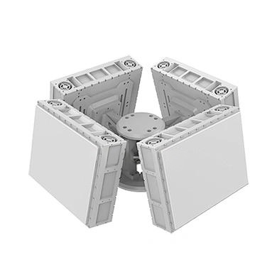
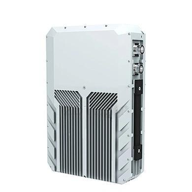
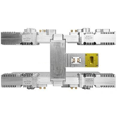
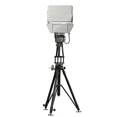
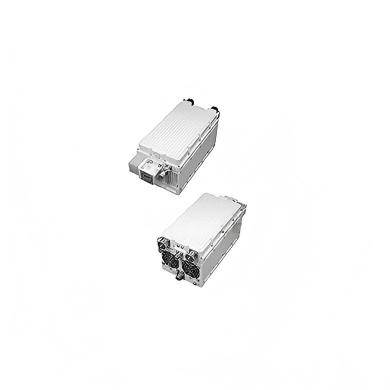
nnIn the rapidly evolving landscape of radar and satellite communication, the demand for compact, high-performance antenna systems has never been greater. Enter the X-band phased array antenna, a cutting-edge solution designed to meet the rigorous requirements of modern defense and aerospace applications. Operating within the 9.2-9.8 GHz frequency range, this advanced antenna supports single-beam, time-division duplex transmission and reception in pulse mode, with a maximum duty cycle of 20% and a pulse width of 20 μs. Its architecture is built for efficiency, reliability, and precision, making it an ideal building block for complex radar front-end systems.nnAt the heart of this system is a two-dimensional active chip-based phased array, integrating 256 tightly arranged radiating elements in a 16×16 orientation and pitch configuration. The entire assembly fits within a remarkably compact 18 mm × 18 mm form factor, achieved through an advanced surface-mount architecture with vertical polarization. This high integration density not only saves space but also reduces weight, enabling deployment in size-constrained platforms such as unmanned aerial vehicles, mobile radar stations, and satellite payloads.nn
Intelligent Beam Control and Protection Features
nnOne of the standout capabilities of this X-band phased array antenna is its intelligent beam control and telemetry system. Each of the 256 channels features independently programmable phase shift and attenuation, allowing for flexible beamforming and precise single-channel on/off control. This granularity ensures that the antenna can adapt its radiation pattern in real time to track targets, mitigate interference, or optimize coverage. Whether scanning across ±45° in azimuth or ±40° in elevation, the system delivers consistent pattern performance with minimal degradation.nnEqually important are the built-in protection mechanisms. The antenna includes overvoltage, overcurrent, and timing disorder protection, ensuring robust and fail-safe operation even under abnormal control sequences. These safeguards are critical in high-stakes environments where a single electrical fault could compromise an entire mission. Additionally, the antenna supports a low-power standby mode that keeps the RF control chip powered while disabling the RF signal path, significantly reducing energy consumption during idle periods.nn
Real-Time Monitoring and Thermal Management
nnThe telemetry system also reports real-time operating temperatures of the TR components, enabling proactive thermal management. This data is invaluable for maintaining peak performance and preventing thermal runaway, especially during extended transmit operations at a 20% duty cycle. The fan control interface integrates seamlessly, allowing operators to set fan speeds to 0%, 50%, or 100% and monitor fan status for normal operation or fault conditions. This level of control ensures the antenna remains within optimal thermal ranges, extending its operational lifespan.nn
Performance Specifications and Beam Characteristics
nnWhen discussing the X-band phased array antenna, performance metrics speak volumes. At broadside, the typical beamwidth is 6.8°±0.6° for transmission (unweighted) and 5.7°±0.8° for reception (weighted). The receiving state, when weighted, achieves a sum beam sidelobe level of ≤ −22 dB in both azimuth and elevation, while the difference beam null depth also reaches ≤ −22 dB. This exceptional sidelobe suppression minimizes false targets and enhances clutter rejection, making the antenna ideal for high-resolution radar imaging and tracking.nnTo present the full technical specifications clearly, the following table encapsulates all critical parameters:nn
| Parameter | Specification |
|---|---|
| Array Architecture | Two-dimensional active chip-based phased array |
| Array Scale | 16×16 (256 radiating elements) |
| Operating Bandwidth | 9.2 GHz – 9.8 GHz |
| Scan Range | Azimuth: ±45°; Elevation: ±40° |
| Beamwidth (Receiving, Weighted, Normal) | Azimuth: 6.8° ± 0.6°; Elevation: 6.8° ± 0.6° |
| Beamwidth (Transmitting, Unweighted, Normal) | Azimuth: 5.7° ± 0.5°; Elevation: 5.7° ± 0.5° |
| Receive Sum Beam Sidelobe Level | Azimuth: ≤ −22 dB (Weighted); Elevation: ≤ −22 dB (Weighted) |
| Receive Difference Beam Null Depth | Azimuth: ≤ −22 dB; Elevation: ≤ −22 dB |
| Maximum Transmit Duty Cycle | ≥ 20% |
| Maximum Pulse Width | 20 μs |
| G/T | ≥ −0.8 dB/K (Normal) |
| EIRP | ≥ 78 dBm (Normal) |
| Power Consumption | ≤ 220 W @ 20% transmit duty cycle |
| Transmit Excitation Power | ≥ 30 dBm |
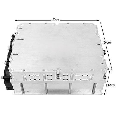
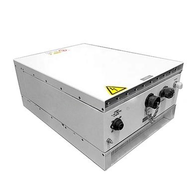
| Size | ≤ 315 mm (pitch) × 315 mm (azimuth) × 60 mm (thickness) |
| Weight | ≤ 6 kg |
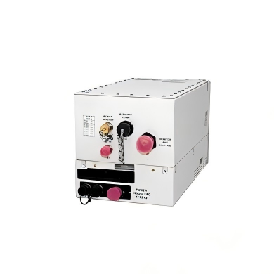
| Power Supply Input Voltage | DC24V to DC30V |
| Total Power Input Current | Determined by power supply requirements |
| RF Interfaces | SMA-K (Azimuth port, Pitch difference port, and And Kou) |
| Fan Control Interface | Fan speed: 0/50%/100%; Fan status: Normal or fault |
nn
Conclusion: A Scalable Foundation for Advanced Systems
nnIn summary, the X-band phased array antenna represents a paradigm shift in radar front-end design. Its high integration density, lightweight surface-mount packaging, and comprehensive environmental protection features make it a scalable, high-reliability building block for radar antenna systems. With an EIRP of ≥78 dBm and a G/T of ≥–0.8 dB/K, it delivers the power and sensitivity needed for demanding satellite communication and radar applications. Whether deployed as a standalone unit or integrated into larger arrays, this subarray offers the flexibility, performance, and durability that modern defense and aerospace sectors demand. The X-band phased array antenna is not just a component; it is the cornerstone of next-generation radar and communication systems.