Why Understanding the Electrical and Mechanical Parameters of Your Antenna Matters
nn
When designing or deploying a reliable communication system, the antenna is often the unsung hero. Whether you’re working on a cellular network, IoT infrastructure, or public safety radio, the antenna’s electrical and mechanical parameters dictate coverage, signal clarity, and durability. Many engineers and installers overlook how factors like frequency range, VSWR, and polarization directly affect real-world performance. By mastering these specifications, you can avoid costly signal loss, interference, and system downtime.
nn
An antenna that looks good on paper may not perform in the field if you ignore key parameters such as intermodulation distortion, beamwidth, or environmental resistance. In this article, we break down the essential electrical and mechanical parameters that define a high-performance vertical antenna, helping you choose the right component for your project.
nn
Exploring Key Electrical Parameters
nn
The electrical behavior of an antenna determines how efficiently it transmits and receives radio frequency (RF) energy. Below, we examine the critical electrical parameters that influence system performance across two common operational bands.
nn
Frequency Range and Impedance Matching
nn
Modern antennas must cover multiple bands to support technologies like 4G, 5G, and LTE. The antenna we are analyzing operates across two distinct frequency ranges: 698–960 MHz and 1710–2700 MHz. These spans cover low-band and high-band cellular services, including extended range and capacity layers. A VSWR (Voltage Standing Wave Ratio) of ≤1.8 across both bands indicates excellent impedance matching, meaning less reflected power and more energy delivered to the air. The input impedance is a standard 50 Ω, which aligns with almost all radio and cable systems.
nn
Polarization and Beamwidth
nn
Vertical polarization (V) is used in this design, which is common for omnidirectional cellular base station antennas. This polarization helps reduce cross-polar interference and improves compatibility with handset antennas. The horizontal beamwidth is a full 360°, providing truly omnidirectional coverage. In contrast, the vertical beamwidth varies from 85° at low frequencies to 35° at high frequencies, allowing the antenna to focus energy more tightly at higher bands. This variation is intentional—it helps balance coverage distance and capacity.
nn
Gain and Intermodulation Performance
nn
Gain values differ by band: 2 dBi in the lower band and 3–5 dBi in the upper band. This gain increase at higher frequencies helps compensate for path loss. Intermodulation (IM3) is a critical distortion metric for multi-carrier systems. With a specification of ≤-107 dBm at 2×33 dBm carriers, this antenna offers low passive intermodulation, which is essential for minimizing interference in dense RF environments. Maximum input power protection is rated at 50 watts, making it suitable for small to medium power applications.
nn
| Parameter | Frequency Band 1 (698–960 MHz) | Frequency Band 2 (1710–2700 MHz) |
|---|---|---|
| VSWR | ≤1.8 | ≤1.8 |
| Input Impedance (Ω) | 50 | 50 |
| Polarization | V | V |
| Gain (dBi) | 2 | 3–5 |
| Horizontal -3 dB Beamwidth (°) | 360 | 360 |
| Vertical -3 dB Beamwidth (°) | 85 | 35 |
| Intermodulation IM3 (2×33 dBm) | ≤-107 dBm | ≤-107 dBm |
| Max Input Protection (W) | 50 | 50 |
nn
How Mechanical Parameters Affect Long-Term Reliability
nn
While electrical parameters define how the antenna performs, mechanical parameters determine whether it survives in the field. Outdoor antennas face rain, wind, UV radiation, and temperature swings. The following specifications highlight what makes this design robust.
nn
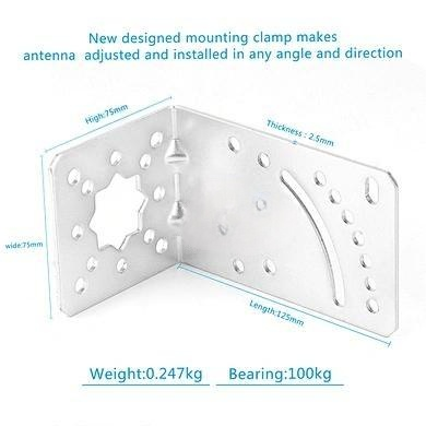
Weight, Materials, and Environmental Resistance
nn
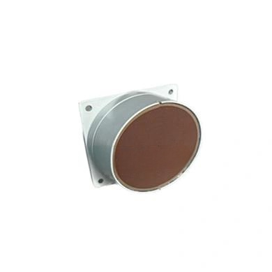
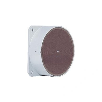
Weighing only 0.5 kg, this antenna is lightweight enough for pole or wall mounting without heavy structural support. The cover material is ABS (Acrylonitrile Butadiene Styrene), a durable plastic that offers excellent impact resistance, UV stability, and weatherproofing. Such material choices are critical for maintaining signal integrity over years of outdoor exposure. The operating temperature range spans from -40°C to +60°C, covering extreme cold and heat found in most regions.
nn
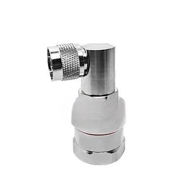
Connector and Lightning Protection
nn
The antenna uses two N-Female connectors, which are standard for professional RF installations and provide secure, weather-resistant connections. Importantly, lightning protection is implemented through a DC ground path. This means the antenna’s DC circuit is grounded, shunting potentially destructive currents from lightning strikes or static buildup safely to earth. This feature is not just a convenience—it is a safety requirement for any outdoor antenna installation.
nn
| Mechanical Parameter | Value |
|---|---|
| Weight (kg) | 0.5 |
| Cover Material | ABS |
| Operating Temperature (°C) | -40 to +60 |
| Connector | 2x N-Female |
| Lightning Protection | DC Ground |
nn
Best Practices for Using These Electrical and Mechanical Parameters
nn
Understanding these electrical and mechanical parameters is only the first step. Apply this knowledge by matching the frequency range to your licensed or unlicensed bands. Verify that VSWR remains below 1.8 across your setup, especially if you add cables or filters. Ensure grounding is properly installed to leverage the DC ground lightning protection. Also, use the intermodulation data to predict performance in high-density sites. When mounting, note the omnidirectional coverage pattern—avoid placing metal objects near the antenna that could distort the 360° beamwidth.
nn
By paying attention to all electrical and mechanical parameters—not just gain or frequency—you can deploy an antenna system that delivers strong, reliable, and safe performance for years.