Unlocking Superior Signal Performance: A Deep Dive into the Cross-Polarized Panel Antenna
nn
In the ever-evolving landscape of wireless communication, the demand for reliable, high-speed connectivity is relentless. Whether for public safety networks, cellular enhancement, or point-to-point links, the antenna at the heart of the system is a critical determinant of overall performance. Among the most powerful and versatile solutions is the Panel Antenna—engineered to deliver exceptional coverage and capacity in demanding environments. This article explores the technical prowess and design philosophy behind a sophisticated dual-polarized panel antenna, revealing how its advanced characteristics ensure robust, interference-free operation across a wide range of applications.
nn
What is a Panel Antenna and Why Polarization Matters?
nn
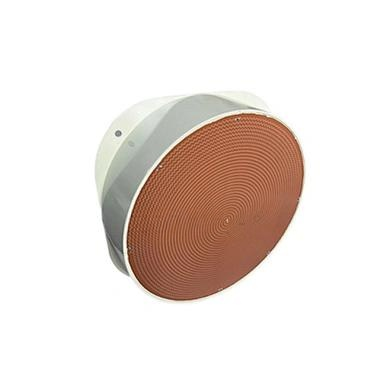
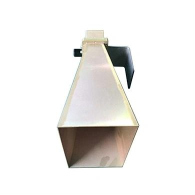
A panel antenna is a flat, rectangular antenna often used for directional or omnidirectional coverage in cellular and Wi-Fi systems. Its low-profile design makes it discreet yet highly effective. The true innovation lies in its cross-polarized antenna technology. By incorporating both Vertical and Horizontal polarizations simultaneously, this antenna dramatically reduces signal fading caused by multipath interference—a common issue in urban and indoor environments. This dual-polarity design also doubles the data throughput potential in MIMO (Multiple-Input, Multiple-Output) systems, making it an essential component for 4G and 5G networks. The dedicated Cross-polar ratio specification, with values of ≥15 dB at 0° and ≥10 dB at ±60°, ensures that the two polarization paths remain well-isolated, minimizing crosstalk and preserving signal integrity even when the device is tilted or mounted at an angle.
nn
Key Specifications of the High-Performance Panel Antenna
nn
To truly appreciate the engineering behind this antenna, one must examine its electrical and mechanical characteristics. The following table provides a comprehensive overview of its core parameters, demonstrating its ability to operate across multiple frequency bands with minimal loss and maximum efficiency. All technical specifications are detailed below.
nn
| Parameter | Value |
|---|---|
| Polarization | Vertical and Horizontal |
| Frequency Range (MHz) | 698 – 4000 |
| Gain (dBi) | 2 – 5 |
| Half-Power Beam Width (°) – Horizontal | H: 360 |
| Half-Power Beam Width (°) – Vertical | V: 90 / 60 (selectable) |
| Voltage Standing Wave Ratio (V.S.W.R.) | ≤ 1.8 |
| Third-Order Intercept Point (dBm) | ≤ -107 |
| Isolation Between Ports (dB) | ≥ 25 |
| Cross-Polar Ratio (dB) | ≥ 15 @ 0° ; ≥ 10 @ ±60° |
| Input Impedance (Ω) | 50 |
| Maximum Input Power (W) | 50 |
| Lightning Protection | DC Ground |
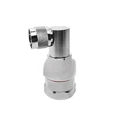
| Input Connector Type | 4.3-10-Female |
| Dimensions (mm) | Φ195 × 102 |
| Antenna Weight (kg) | 0.45 |
| Operating Temperature (°C) | -40 to 60 |
| Radome Material | ABS |
| Radome Color | White |
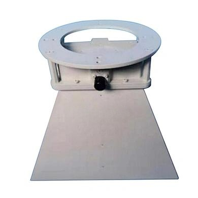
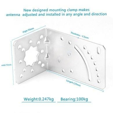
| Mounting Pole Way | Fastened with screw nuts |
nn
Why Choose This Panel Antenna for Your Network?
nn
The engineering excellence of this cross-polarized antenna is evident in every specification. Its ability to cover an exceptionally broad frequency range—from 698 MHz to 4 GHz—makes it a truly future-proof investment, supporting everything from legacy LTE bands to modern CBRS and 5G NR bands. The high isolation between ports (≥25 dB) guarantees that the Vertical and Horizontal paths do not interfere with each other, which is critical for maintaining high signal-to-noise ratios in dense environments. Furthermore, the antenna’s robust mechanical construction, including an ABS radome and a compact, lightweight design (only 0.45 kg), ensures it can withstand harsh outdoor conditions (-40°C to 60°C) while being easy to install. The 4.3-10-Female connector is a modern, industry-standard interface known for its excellent passive intermodulation (PIM) performance and reliability under high vibration.
nn
Maintaining Signal Integrity in Real-World Conditions
nn
Real-world deployment scenarios—such as on a rooftop, a utility pole, or inside a parking structure—introduce challenges like signal reflection and polarization mismatch. This panel antenna’s exceptional Cross-polar ratio and low V.S.W.R. (≤1.5 for the second output) work in tandem to minimize interference. The half-power beam width can be configured to either 90° or 60° vertical tilt, allowing the installer to fine-tune the coverage pattern for optimal signal distribution. Combined with a DC ground for lightning protection, this antenna provides a complete, worry-free solution for critical communications. Its mounting system, using screw nuts, allows for rapid, secure attachment to standard poles without specialized tools.
nn
Conclusion: The Ideal Choice for Reliable Wireless Infrastructure
nn
In summary, this meticulously engineered panel antenna stands as a benchmark for performance, versatility, and durability. By integrating dual polarization with a wide frequency range, high gain, and exceptional electrical isolation, it solves the most persistent challenges in wireless connectivity. Whether you are upgrading a cellular base station, deploying a private LTE network, or optimizing an indoor DAS system, this antenna delivers. Its specification set—ranging from 2-5 dBi gain to a 50 Ω impedance—demonstrates a commitment to quality that translates directly into clearer voice calls, faster data speeds, and more reliable connections. For any organization striving for superior wireless coverage, this cross-polarized panel antenna is not just a choice—it is the foundation of a high-performance network.