Understanding High-Performance Power Splitters for Modern Networks
nn
In the demanding world of telecommunications and wireless infrastructure, signal distribution must be both precise and reliable. Power splitters are the unsung heroes that divide a single input signal into multiple output signals without significant loss or distortion. For engineers and system integrators seeking robust solutions, the MOP-PS series offers two distinct models tailored to different frequency and performance requirements. This article explores the key features, technical specifications, and ideal use cases for these advanced passive components, providing a comprehensive guide for selecting the right power splitter for your application.
nn
Introducing the MOP-PS-727 and MOP-PS-740 Series
nn
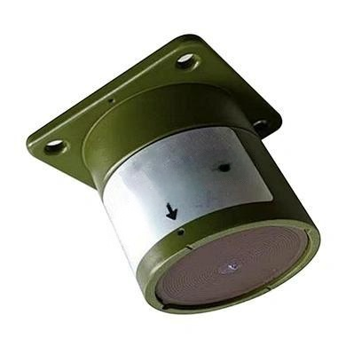
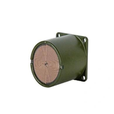
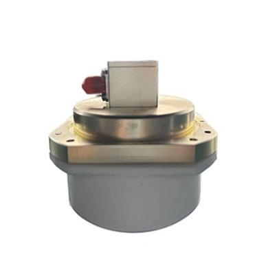
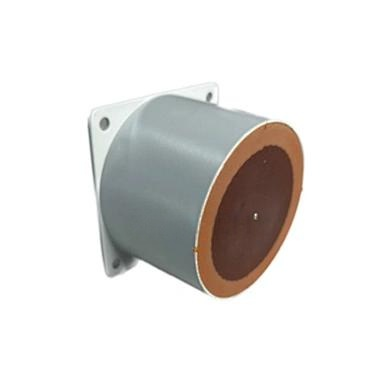
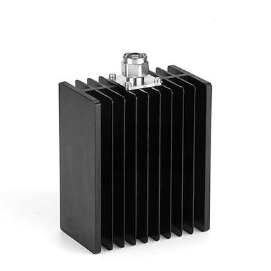
The power splitter models MOP-PS-727-200(300/500)-XXNF(MF/DF) and MOP-PS-740-200(300/500)-XXNF(MF/DF) are engineered to meet the rigorous demands of modern cellular, DAS, and small cell networks. Whether for indoor coverage solutions or outdoor base station deployments, these units ensure consistent signal integrity across multiple output paths. Their design prioritizes low insertion loss, excellent voltage standing wave ratio (VSWR), and high intermodulation performance, making them ideal for high-capacity 4G/LTE and emerging 5G networks.
nn
Technical Specifications and Performance Data for the MOP-PS-727 Power Splitter
nn
Both models offer a range of split ways and power handling options (200W, 300W, or 500W). Below, we break down the core specifications for the MOP-PS-727 series, which operates from 698 MHz to 2700 MHz.
nn
| Parameter | Value (2-Way) | Value (3-Way) | Value (4-Way) |
|---|---|---|---|
| Frequency Range | 698-2700 MHz | 698-2700 MHz | 698-2700 MHz |
| Split Way | 2 | 3 | 4 |
| VSWR | ≤1.25:1 | ≤1.25:1 | ≤1.25:1 |
| Insertion Loss (dB) | ≤3.3 | ≤5.2 | ≤6.4 |
| Average Power (W) | 200 / 300 / 500 | 200 / 300 / 500 | 200 / 300 / 500 |
| 3rd Order IMD (dBc) | ≤ -155 @ 2×43 dBm | ≤ -155 @ 2×43 dBm | ≤ -155 @ 2×43 dBm |
| Impedance (Ω) | 50 | 50 | 50 |
| Connectors | Type N or 4.3-10 DIN-Female | Type N or 4.3-10 DIN-Female | Type N or 4.3-10 DIN-Female |
| Operation Temperature (°C) | -20 to +55 | -20 to +55 | -20 to +55 |
| Application | Indoor or Outdoor | Indoor or Outdoor | Indoor or Outdoor |
nn
Technical Specifications and Performance Data for the MOP-PS-740 Power Splitter
nn
The MOP-PS-740 series extends frequency coverage up to 3800 MHz, making it suitable for higher-band 5G and specialized applications. While maintaining similar power options, this model offers slightly different insertion loss and intermodulation characteristics optimized for broader bandwidth.
nn
| Parameter | Value (2-Way) | Value (3-Way) | Value (4-Way) |
|---|---|---|---|
| Frequency Range | 698-3800 MHz | 698-3800 MHz | 698-3800 MHz |
| Split Way | 2 | 3 | 4 |
| VSWR | ≤1.25:1 | ≤1.25:1 | ≤1.25:1 |
| Insertion Loss (dB) | ≤3.5 | ≤5.5 | ≤7.0 |
| Average Power (W) | 200 / 300 / 500 | 200 / 300 / 500 | 200 / 300 / 500 |
| 3rd Order IMD (dBc) | ≤ -150 @ 2×43 dBm | ≤ -150 @ 2×43 dBm | ≤ -150 @ 2×43 dBm |
| Impedance (Ω) | 50 | 50 | 50 |
| Connectors | Type N or 4.3-10 DIN-Female | Type N or 4.3-10 DIN-Female | Type N or 4.3-10 DIN-Female |
| Operation Temperature (°C) | -25 to +65 | -25 to +65 | -25 to +65 |
| Application | Indoor or Outdoor | Indoor or Outdoor | Indoor or Outdoor |
nn
Key Performance Considerations for Your Power Splitter
nn
When selecting a power splitter, several factors directly impact network performance. The MOP-PS series excels in three critical areas: insertion loss, VSWR, and intermodulation distortion (IMD). Insertion loss, as shown in the tables, increases with the number of output ports. For example, a 2-way splitter typically loses only 3.3 dB, while a 4-way unit may lose up to 6.4 dB (MOP-PS-727) or 7.0 dB (MOP-PS-740). This is a reasonable trade-off for signal distribution in dense environments. The VSWR of ≤1.25:1 ensures excellent impedance matching, minimizing signal reflections and maintaining clean transmission. Furthermore, the 3rd order IMD performance—≤ -155 dBc for the 727 series and ≤ -150 dBc for the 740 series—keeps interference at bay in high-power, multi-carrier scenarios.
nn
Application Flexibility: Indoor and Outdoor Use
nn
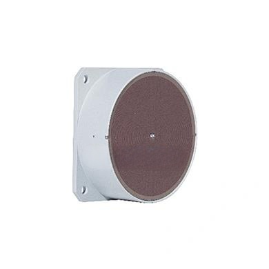
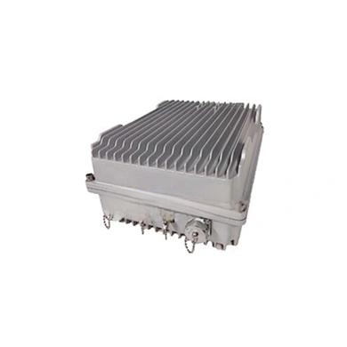
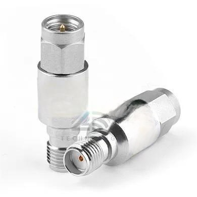
Both the MOP-PS-727 and MOP-PS-740 are rated for indoor or outdoor installation, giving you deployment flexibility. The MOP-PS-727’s operating temperature range of -20°C to +55°C is suitable for most indoor environments and sheltered outdoor cabinets. The MOP-PS-740, with its extended range of -25°C to +65°C, is better suited for harsh outdoor conditions where temperature extremes are common. The choice of connectors—either Type N or 4.3-10 DIN-Female—allows compatibility with standard cables and equipment. For installations exposed to weather, the 4.3-10 interface offers superior PIM performance and weatherproofing.
nn
Selecting the Optimal Power Splitter for Your Network
nn
To recap, the power splitter you choose will depend on your frequency requirements and desired split configuration. For networks operating up to 2700 MHz—typical for LTE and early 5G bands—the MOP-PS-727 provides excellent performance with lower insertion loss and superior IMD suppression. For deployments requiring coverage up to 3800 MHz, such as C-band 5G, the MOP-PS-740 is the clear choice, despite its slightly higher insertion loss and relaxed IMD specs. The model name suffixes (200, 300, 500) indicate average power handling, and the connector options (NF for Type N Female, MF for 4.3-10 Female, DF for DIN Female) provide further customization. By carefully matching these parameters to your specific system topology, you ensure optimal signal distribution, low distortion, and long-term reliability. Whether you’re upgrading an existing DAS or building out a new small cell network, the MOP-PS series delivers the engineering excellence required for modern, high-performance communications.