Understanding the Interface Model MOP-CN-DM-CF78: A Comprehensive Guide to RF Connectivity
nn
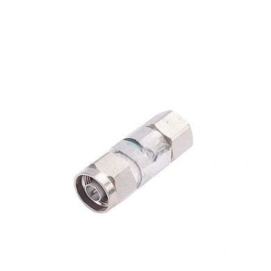
In the world of radio frequency (RF) and microwave engineering, the reliability and performance of connectors are paramount. The Interface Model MOP-CN-DM-CF78 stands out as a robust solution designed for demanding applications that require low signal loss and consistent impedance. This article delves into the intricate details of this connector, highlighting its electrical, mechanical, and environmental specifications. By understanding the full picture of this interface, engineers and technicians can make informed decisions for their coaxial cable assemblies and RF systems. Let’s explore what makes this model a preferred choice in high-frequency environments.
nn
The Interface Model MOP-CN-DM-CF78 is engineered to maintain signal integrity over a broad frequency range. Its design prioritizes low Voltage Standing Wave Ratio (VSWR) and minimal passive intermodulation (PIM), which are critical for modern telecommunications, aerospace, and test equipment. The following sections break down the key performance metrics, ensuring you have a clear grasp of its capabilities and suitability for your specific project.
nn
Electrical Characteristics of MOP-CN-DM-CF78
nn
The electrical performance of any RF connector is its most vital attribute. The MOP-CN-DM-CF78 is built to handle high-power signals with exceptional stability. Below, we outline the core electrical specifications that define its reliability.
nn
Impedance and Frequency Range
n
Operating at a characteristic impedance of 50 ohms, this interface is perfectly matched to the industry standard for most RF systems. It supports a frequency range from DC up to 6 GHz, making it suitable for a wide variety of applications including wireless infrastructure, base stations, and satellite communications. This broad bandwidth ensures that the connector does not introduce distortion or signal reflections within its operating spectrum.
nn
VSWR and Dielectric Performance
n
With a VSWR rating of ≤1.15, the connector achieves excellent return loss. This low value means that very little power is reflected back toward the source, maximizing the efficiency of signal transmission. Additionally, the dielectric strength is substantial, withstanding up to ≥2500V RMS at 50 Hz (at sea level), while the insulation resistance remains above ≥5000 MΩ. These factors collectively ensure safe operation under high voltage conditions and prevent arcing.
nn
Contact Resistance and Passive Intermodulation (PIM)
n
Minimizing resistance at connection points is crucial for reducing heat generation and signal degradation. The contact resistance for both the outer and center conductors is specified at ≤1.0 mΩ, ensuring low loss. Furthermore, the Passive Intermodulation (PIM) performance is exceptional, rated at ≤-155 dBc. This low PIM level is essential for maintaining signal clarity in multi-channel systems, where intermodulation products can cause interference.
nn
Mechanical Robustness and Material Quality
nn
A connector’s longevity depends heavily on its mechanical design and the materials used in its construction. The MOP-CN-DM-CF78 is built to endure repeated use and harsh conditions.
nn
Durability and Mating Cycles
n
The interface is designed for a minimum of 500 mating cycles, demonstrating a robust mechanical lifecycle. This ensures that the connector can withstand frequent disconnection and reconnection in testing or maintenance scenarios without degrading performance.
nn
Material Composition and Plating
n
Premium materials are selected to resist corrosion and maintain conductivity. The body is crafted from brass with a tri-alloy plating, offering a balance of strength and signal integrity. The insulator uses PTFE (Teflon), known for its excellent dielectric properties and temperature resistance. The center conductor is made from a combination of phosphor bronze and beryllium bronze, plated with silver for superior electrical performance. Other components also utilize brass with a nickel plating for additional environmental protection.
nn
Environmental Specifications and Operating Conditions
nn
For equipment deployed in outdoor or variable environments, temperature stability is crucial. The Interface Model MOP-CN-DM-CF78 can reliably operate across a temperature range of -40°C to +85°C. This wide tolerance ensures dependable performance in both cold climates and high-temperature industrial settings, making it a versatile choice for global deployment.
nn
Technical Data Summary
n
The following table consolidates all critical technical specifications for the MOP-CN-DM-CF78 interface. This structured data provides a quick reference for engineers and procurement specialists.
nn
| Parameter | Value |
|---|---|
| Characteristic Impedance | 50 Ω |
| Frequency Range | DC – 6 GHz |
| VSWR | ≤ 1.15 |
| Dielectric Withstanding Voltage | ≥ 2500 V RMS, 50 Hz (at sea level) |
| Insulation Resistance | ≥ 5000 MΩ |
| Outer Contact Resistance | ≤ 1.0 mΩ |
| Center Contact Resistance | ≤ 1.0 mΩ |
| Passive Intermodulation (PIM3) | ≤ -155 dBc |
| Durability (Mating Cycles) | ≥ 500 |
| Body Material | Brass, Tri-alloy Plating |
| Insulator Material | PTFE |
| Center Conductor Material | Phosphor Bronze + Beryllium Bronze, Ag Plating |
| Other Components Material | Brass, Ni Plating |
| Temperature Range | -40°C to +85°C |
nn
Conclusion: Why the Interface Model MOP-CN-DM-CF78 Delivers Excellence
nn
The Interface Model MOP-CN-DM-CF78 represents a pinnacle of RF connector engineering, combining low VSWR with high durability and excellent environmental tolerance. Its 50-ohm impedance and DC-6 GHz frequency range make it a standard bearer for modern communication systems. The detailed specifications, from contact resistance to PIM performance, confirm its suitability for applications where signal purity is non-negotiable. Whether you are designing a new system or upgrading existing infrastructure, this model offers the quality and consistency needed for reliable operation. By choosing the MOP-CN-DM-CF78, you invest in a component that meets the rigorous demands of the RF industry.