
Unlocking Performance: Essential RF Technical Parameters for High-Power Amplifiers
nnWhen designing or integrating a high-power amplifier system for demanding RF applications, understanding the core technical specifications is critical. This article dives deep into the key parameters that define the performance, reliability, and usability of a wideband amplifier operating between 300 and 1300 MHz. By focusing on the RF technical parameters, you can ensure your system meets stringent requirements for signal integrity and power delivery.nnThe heart of any transmitter chain lies in its ability to boost a weak signal to a robust, usable power level without introducing distortion or instability. From broadcast systems to test instrumentation, the measurable characteristics of the amplifier determine its suitability for the task. We will explore the critical metrics that engineers and technicians must evaluate, including frequency range, output power, gain linearity, and impedance matching.nn
Critical RF Technical Parameters Defined
nnThe amplifier in question delivers a saturated power output of 43±1dBm, which equates to approximately 20 watts. This substantial power is achieved through a gain of 43±2dB, providing a significant boost to any input signal. The in-band flatness and spurious emissions are tightly controlled, ensuring that the output remains clean and within regulatory spectral limits. The following table provides a complete breakdown of the essential RF technical parameters for this high-power amplifier module.nn
| Parameter | Technical Specification |
|---|---|
| Working Frequency | 300 – 1300 MHz |
| Saturated Power Output | 43 ± 1 dBm |
| Gain | 43 ± 2 dB |
| In-Band Flatness | Indicated per application |
| Working Current | Indicated per application |
| Input & Output VSWR | ≤ 1.5 |
| Out-of-Band Spurs (9 kHz – 1 GHz) | ≤ -36 dBm / 30 kHz |
| Out-of-Band Spurs (1 GHz – 12.75 GHz) | ≤ -30 dBm / 30 kHz |
| Maximum Lossless Input | +10 dBm |
| Operating Voltage | DC +28 V |
| Power Supply Interface | Feed-through Capacitor |
| RF Port (RFIN / RFOUT) | SMA-KFD |
| Monitoring Interface | Feed-through Capacitor |
nn
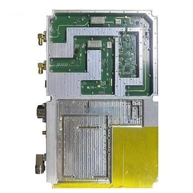
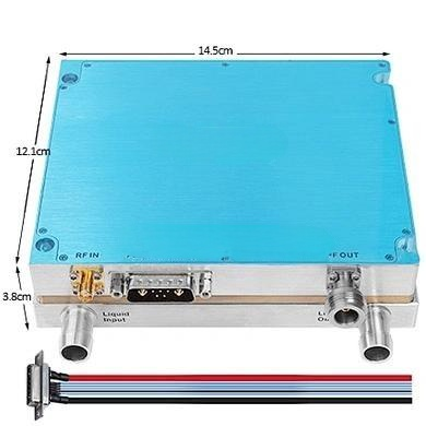
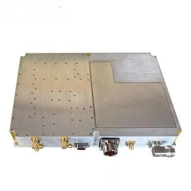
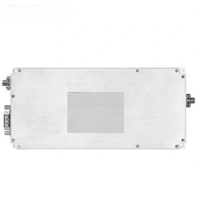
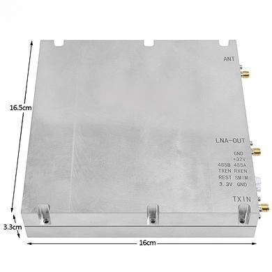
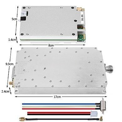
Mechanical Design and Environmental Considerations
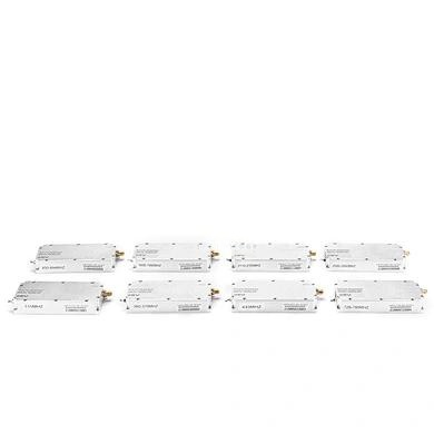
nnBeyond the electrical performance, the physical and environmental characteristics are equally important for integration into a system. The compact amplifier measures just 135 x 67 x 20 mm, making it suitable for space-constrained enclosures. It is designed to operate reliably across a temperature range of -10 to +55°C with relative humidity up to 95% non-condensing. Storage temperature extends from -25 to +65°C, ensuring longevity in varied conditions.nn
Why These RF Technical Parameters Matter in Practice
nnUnderstanding these RF technical parameters is crucial for system optimization. The low VSWR of ≤1.5 indicates excellent impedance matching, minimizing reflected power and protecting the amplifier stages from damage. The tight control over out-of-band spurs ensures compliance with stringent EMC regulations, making the unit suitable for sensitive measurement environments. The use of a feed-through capacitor for the power supply and monitoring interface allows for clean DC injection and minimal RF leakage, a hallmark of professional-grade RF design.nnIn conclusion, whether you are selecting an amplifier for a wireless communication system, a radar driver, or an EMC test setup, paying close attention to these RF technical parameters will guide you to the right component. The combination of high power output, wide bandwidth, and robust construction, as detailed in the specifications above, provides a solid foundation for high-performance RF applications. Always verify your system-level requirements against each parameter to ensure seamless integration and optimal operational efficiency.