Interface Model MOP-CN-DM-CF78S: A High-Performance RF Connector Solution
n
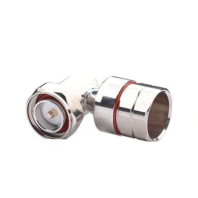
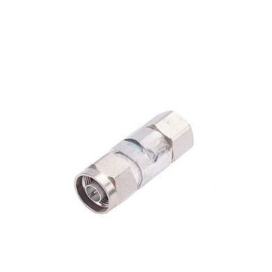
In the world of RF and microwave technology, the quality of connectors can make or break a system’s performance. The Interface Model MOP-CN-DM-CF78S stands out as a robust, precision-engineered component designed for demanding applications. Whether you are working on telecommunications infrastructure, test equipment, or aerospace systems, this connector delivers exceptional electrical and mechanical reliability. Its advanced design ensures minimal signal loss, high durability, and consistent performance across a wide frequency range. Let’s dive into the critical specifications that make this model a top choice for engineers and technicians.
nn
Electrical Characteristics of the MOP-CN-DM-CF78S
n
The electrical performance of the MOP-CN-DM-CF78S is tailored for high-frequency applications where signal integrity is paramount. With a characteristic impedance of 50 ohms, it aligns with industry standards for RF systems, ensuring compatibility with cables, antennas, and other components. The frequency range extends from DC to 6 GHz, covering a broad spectrum used in wireless communications, radar, and satellite systems. The voltage standing wave ratio (VSWR) is ≤1.15, which minimizes reflections and power loss, while the dielectric withstanding voltage is ≥2500V RMS at 50 Hz at sea level, providing a safety margin for high-voltage environments. Additionally, dielectric resistance exceeds 5000MΩ, preventing leakage currents. Contact resistance is kept ultra-low at ≤1.0mΩ for both outer and center contacts, ensuring efficient power transfer. Passive intermodulation (PIM3) is ≤-155dBc, which is critical for reducing interference in multi-carrier systems.
nn
Key Electrical Parameters at a Glance
n
| Parameter | Value |
|---|---|
| Characteristic Impedance | 50 ohm |
| Frequency Range | DC-6 GHz |
| VSWR | ≤ 1.15 |
| Dielectric Withstanding Voltage | ≥2500V RMS, 50 Hz, at sea level |
| Dielectric Resistance | ≥5000MΩ |
| Contact Resistance (Outer) | ≤1.0 mΩ |
| Contact Resistance (Center) | ≤1.0 mΩ |
| PIM3 | ≤ -155 dBc |
nn
Mechanical Durability and Environmental Resilience
n
Beyond electrical specs, the MOP-CN-DM-CF78S is built to withstand repeated use and harsh conditions. The connector supports a minimum of 500 mating cycles, ensuring long-term reliability in test setups or field installations. Temperature stability is maintained from -40°C to +85°C, making it suitable for both cold climates and hot environments. The materials and plating are carefully chosen to resist corrosion, wear, and signal degradation. The body uses brass with a tri-alloy plating for conductivity and strength, while the insulator is made of PTFE for excellent dielectric properties. The center conductor combines phosphor bronze and beryllium bronze with silver plating to optimize signal transfer and durability. Other components are brass with nickel plating for added protection.
nn
Material and Plating Specifications
n
| Component | Material | Plating |
|---|---|---|
| Body | Brass | Tri-alloy |
| Insulator | PTFE | – |
| Center Conductor | Phosphor bronze + Beryllium bronze | Ag (Silver) |
| Other | Brass | Ni (Nickel) |
nn
Why the MOP-CN-DM-CF78S Matters in Modern RF Systems
n
The integration of the MOP-CN-DM-CF78S into your RF chain brings tangible benefits. Its low VSWR and contact resistance reduce signal loss, while the high PIM performance minimizes distortion in sensitive applications. The wide temperature range and robust materials ensure that the connector performs consistently over time, even in challenging environments. For engineers designing 5G networks, broadcasting equipment, or military communications, this component offers a balance of precision and reliability. The focus keyword highlights the model’s identity, but its real value lies in the engineering details that ensure seamless connectivity.
nn
Testing and Validation Considerations
n
When deploying the MOP-CN-DM-CF78S, always verify that mating connectors meet the 50-ohm impedance and that torque specifications are followed to maintain low contact resistance. The 500-cycle durability means the connector is suitable for repeated connections in lab or production settings. For high-voltage applications, the dielectric withstanding voltage provides a safety buffer, but proper insulation and grounding are still essential. The focus keyword here reminds us that the model is a specific solution, but its technical pedigree ensures broad applicability.
nn
Conclusion
n
The Interface Model MOP-CN-DM-CF78S is more than just a connector—it is a precision tool for RF engineers who demand the best in signal integrity and reliability. From its 50-ohm impedance and DC-6 GHz frequency range to its durable materials and environmental resilience, every aspect is designed for high-performance use. By understanding its electrical, mechanical, and material characteristics, you can confidently integrate this component into your systems and trust that it will deliver consistent results. The focus keyword underscores the model’s unique specifications, but the ultimate takeaway is its role in enabling superior RF connectivity in demanding applications.