Introduction: Understanding the MOP-OCA Series Indoor Omni Antennas
n
Modern wireless networks demand seamless coverage, especially in indoor environments where signal distribution can be challenging. The MOP-OCA-740-4/5NF(MF/DF) and MOP-OCA-727-4/5NF(MF/DF) antennas offer robust omnidirectional performance for a wide range of applications, from public venues to enterprise spaces. This article delves into their Electrical Specifications, mechanical features, and thermal resilience, providing a clear comparison to help you select the right model for your deployment. Whether you are expanding a cellular network or upgrading Wi-Fi infrastructure, these antennas deliver reliable connectivity across multiple frequency bands.
n
Designed for ceiling mounting and aesthetic integration, the MOP-OCA series balances performance with practicality. The focus keyword, Electrical Specifications, underpins every technical decision, ensuring you understand how frequency range, gain, and power handling impact your network design. Below, we break down each specification in detail, using structured tables for clarity.
nn
Key Electrical Specifications at a Glance
n
The Electrical Specifications of these antennas determine their ability to transmit and receive signals efficiently. Key parameters include frequency coverage, gain, polarization, and impedance matching. Both models share a vertical polarization design and omnidirectional horizontal coverage, but they differ in supported frequency bands and vertical beamwidth.
nn
Frequency Range and Gain
n
The MOP-OCA-740-4/5NF(MF/DF) operates across 698–960 MHz and 1710–4000 MHz, offering dual-band coverage with 2 dBi gain in the lower band and 5 dBi in the higher band. In contrast, the MOP-OCA-727-4/5NF(MF/DF) covers 698–960 MHz and 1710–2700 MHz, with identical gain values. This makes the former more suitable for extended high-frequency applications, such as 3500 MHz or 4000 MHz bands.
nn
Voltage Standing Wave Ratio (VSWR) and Power Handling
n
Maintaining a low VSWR (≤1.8) ensures minimal signal reflection, which is critical for efficient power transfer. Both antennas support up to 50 watts of input power and feature a 50-ohm impedance. The passive intermodulation (PIM) performance is rated at ≤-150 dBc (3rd order, 2 x 20 W), guaranteeing minimal interference for high-quality signal transmission.
nn
| Parameter | MOP-OCA-740-4/5NF(MF/DF) | MOP-OCA-727-4/5NF(MF/DF) |
|---|---|---|
| Frequency Range (MHz) | 698–960 / 1710–4000 | 698–960 / 1710–2700 |
| Gain (dBi) | 2 / 5 | 2 / 5 |
| Polarization | Vertical | Vertical |
| Beamwidth – Horizontal (deg) | 360 | 360 |
| Beamwidth – Vertical (deg) | 85 / 35 | 85 / 35 |
| VSWR | ≤1.8 | ≤1.8 |
| PIM, 3rd Order, 2 x 20 W (dBc) | ≤-150 | ≤-150 |
| Input Power, Max (W) | 50 | 50 |
| Impedance (Ohm) | 50 | 50 |
nn
Mechanical Specifications for Installation and Durability
n
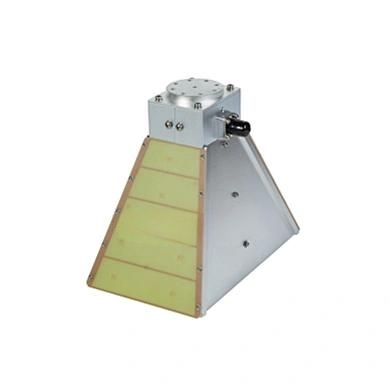
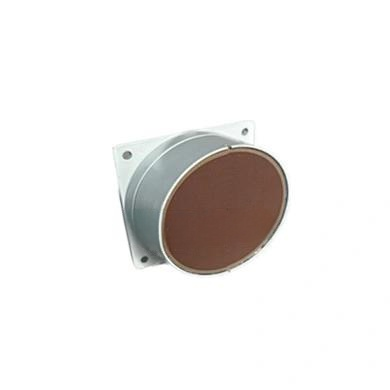
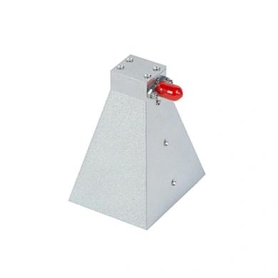
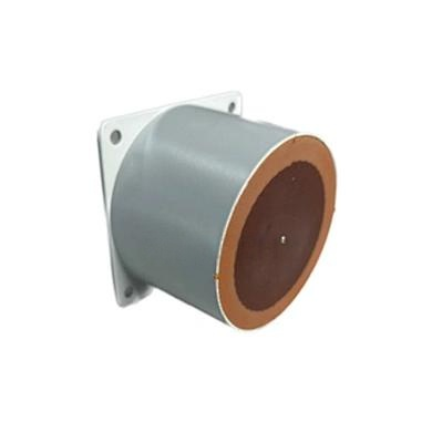
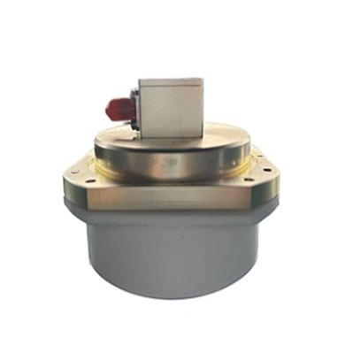
Understanding the mechanical design is just as important as the Electrical Specifications. Both antennas share the same physical footprint, connector options, and mounting method, simplifying inventory management. The compact form factor (Φ172×70 mm, 0.5 kg) allows for discreet ceiling integration without compromising structural integrity.
nn
Connector and Mounting Flexibility
n
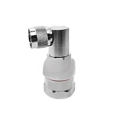
The standard connector is Type N-female, with optional 4.3-10 or 7/16 din variants, ensuring compatibility with common RF cables. Mounting is achieved via a via hole (through-hole) system, securely fastening the antenna to ceiling tiles or solid surfaces. The radome is crafted from ABS plastic with a white RAL9003 finish, blending into modern interiors while protecting against dust and minor impacts.
nn
| Parameter | Value (Both Models) |
|---|---|
| Connector Type | N (4.3-10 or 7/16 din) – Female |
| Dimensions (mm) | Φ172 × 70 |
| Weight (kg) | 0.5 |
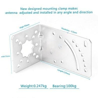
| Mounting Kit | Ceiling, via hole (standard) |
| Radome Material and Color | ABS, White, RAL9003 |
nn
Environmental Resilience: Operational Temperature and Humidity
n
To ensure reliable performance in diverse indoor climates, these antennas are tested across a wide temperature range. Their Electrical Specifications remain stable from -40°C to 55°C, while humidity tolerance reaches 95% (non-condensing). This makes them suitable for unconditioned spaces like warehouses, covered parking, or industrial facilities, pending proper ventilation.
nn
Thermal and Moisture Considerations
n
The ABS radome material resists UV degradation and thermal expansion, maintaining consistent RF performance. For installations in high-humidity environments, ensure the mounting surface allows air circulation to prevent condensation within the via hole. The antenna’s robust construction aligns with IP65 standards, though not explicitly rated—consult the manufacturer for outdoor use cases.
nn
| Environmental Parameter | Value (Both Models) |
|---|---|
| Operational Temperature (°C) | -40 to 55 |
| Operational Humidity (%) | ≤95 (non-condensing) |
nn
Conclusion: Choosing the Right Antenna Based on Electrical Specifications
n
When selecting between the MOP-OCA-740-4/5NF(MF/DF) and MOP-OCA-727-4/5NF(MF/DF), your primary decision hinges on the high-frequency range requirement. The former extends to 4000 MHz, accommodating upcoming 5G bands or regional LTE frequencies, while the latter caps at 2700 MHz—ideal for conventional cellular and Wi-Fi 6E networks. Both models share identical Electrical Specifications for gain, VSWR, and PIM, ensuring consistent performance across shared bands. Combined with their user-friendly mounting and durable build, these antennas offer a reliable solution for indoor omnidirectional coverage. Evaluate your frequency needs, environmental conditions, and connector preferences before deployment to maximize network efficiency.