Understanding the Directional Coupler: A Critical Component for RF Systems
nn
In the world of radio frequency (RF) engineering, precise signal monitoring and distribution are paramount. One of the most essential devices for achieving these tasks is the directional coupler. This component allows engineers to sample a small portion of the RF signal traveling through a transmission line without significantly disturbing the main signal path. Whether you are designing a base station, testing a transmitter, or maintaining a communication network, understanding the specifications and applications of a directional coupler is vital for system performance.
nn
Our focus today is on a specific indoor directional coupler model designed for efficient signal coupling across a broad frequency range. This device seamlessly balances performance with compact design, making it an excellent choice for various telecommunications and laboratory applications. The following sections will break down its features, highlight key technical specifications, and explain why proper selection is crucial for your project’s success.
nn
Key Specifications and Performance Metrics
nn
When evaluating a directional coupler, several parameters define its functionality and suitability for your application. This model operates indoors and is built with durability and reliability in mind. Below, you will find the complete technical data, organized for clarity and easy reference.
nn
| Parameter Category | Specification | Value |
|---|---|---|
| Electrical Specifications | Frequency Range | 50 – 500 MHz |
| VSWR (Voltage Standing Wave Ratio) | ≤ 1.3 | |
| Coupling | 20 dB | |
| Insertion Loss | ≤ 0.4 dB | |
| Directivity | ≥ 20 dB | |
| Ripple in Band | ± 1.0 dB | |
| Impedance | 50 Ohm | |
| Total Input Power | 200 W | |
| Number of Input Ports | 1 | |
| Number of Output Ports | 2 | |
| Connector Type | N-female | |
| Application | Indoor | |
| Mechanical Specifications | Width | 54 mm |
| Depth | 36 mm | |
| Length | 144 mm | |
| Weight | 0.60 Kg | |
| Environmental Specifications | Temperature Range | -30°C to +60°C |
nn
Electrical Performance in Detail
nn
The electrical characteristics of this directional coupler demonstrate a balanced design for reliable signal sampling. With a frequency range spanning 50 to 500 MHz, it covers VHF and UHF bands commonly used in broadcast, PMR, and cellular applications. A low VSWR of ≤ 1.3 ensures minimal signal reflection, which is critical for maintaining system efficiency and protecting sensitive equipment. The 20 dB coupling value provides a suitable signal sample for monitoring or measurement without draining the main line’s power. Additionally, the high directivity of ≥ 20 dB allows this coupler to accurately distinguish between forward and reflected signals, a feature essential for power measurement and antenna tuning.
nn
Mechanical and Environmental Robustness
nn
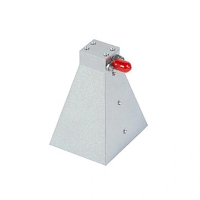
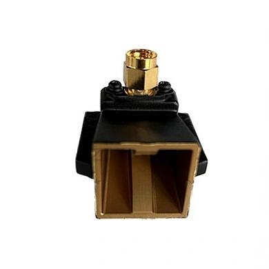
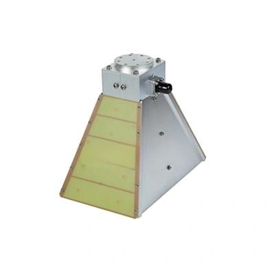
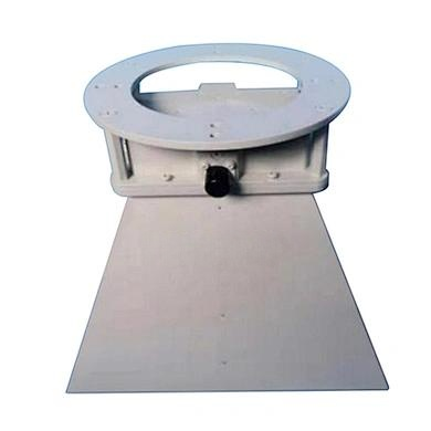
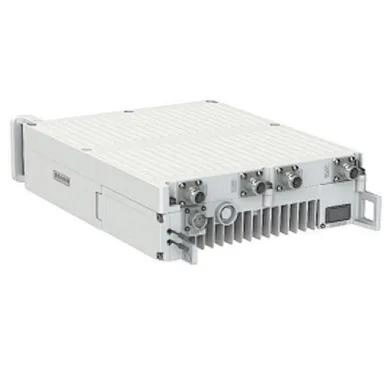
Built for indoor deployment, this directional coupler features a compact enclosure measuring just 144 mm in length, 54 mm in width, and 36 mm in depth. Its lightweight design of 0.60 kg simplifies installation in crowded equipment racks or test setups. The use of N-female connectors ensures robust, weather-resistant connections appropriate for professional environments. Furthermore, the device operates reliably across a wide temperature range of -30°C to +60°C, accommodating diverse indoor climates from cold storage facilities to heated server rooms.
nn
Applications and Benefits of Using This Directional Coupler
nn
This directional coupler excels in multiple roles, making it a versatile tool for RF engineers. Its primary use is in signal monitoring—tapping a portion of the transmitted signal for analysis without interrupting service. It is also ideal for power measurement in transmitter test setups, where the coupled port connects to a power meter. The device is equally valuable in antenna systems, where its directivity helps determine the ratio of forward to reflected power, enabling efficient tuning and reducing signal loss.
nn
Another critical application is in laboratory environments. Engineers rely on directional couplers for device characterization, filter testing, and amplifier linearity measurements. The device’s low insertion loss of ≤ 0.4 dB ensures minimal signal degradation, preserving the integrity of the test setup. For indoor installations, its compact form factor and N-female connectors offer a practical solution with minimal footprint.
nn
Why Proper Selection Matters
nn
Choosing the right directional coupler is not just about matching frequency and coupling values. It involves understanding your system’s specific needs—power handling, connector compatibility, and environmental conditions. Overlooking any parameter can lead to inaccurate readings, signal degradation, or even equipment damage. For instance, using a coupler with insufficient directivity in a monitoring setup may give false readings of reflected power, misleading maintenance efforts. Similarly, exceeding the 200 W power limit can cause overheating or failure.
nn
Conclusion
nn
In summary, this indoor directional coupler stands out for its exceptional electrical performance, robust mechanical design, and versatile application range. Its ability to maintain low VSWR, high directivity, and minimal insertion loss across a broad frequency band makes it a reliable choice for professionals in telecommunications, broadcasting, and RF testing. When you deploy this directional coupler in your system, you gain a precise tool for signal sampling and monitoring, ensuring optimal performance and longevity. Whether for routine measurement or critical antenna tuning, selecting a high-quality directional coupler is a decision that pays dividends in system accuracy and reliability. Always verify that the specifications align with your project requirements to achieve the best results.