MOP Model MOP-AD-MF/MF: A High-Performance 4.3-10 Straight Female to Straight Female Adapter
n
The MOP-AD-MF/MF is a precision-engineered coaxial adapter designed for demanding RF applications. This component provides a reliable bridge between two 4.3-10 straight female interfaces, ensuring minimal signal loss and excellent electrical performance across a wide frequency range. Its robust construction and high-quality materials make it an ideal choice for telecommunications, broadcast, and test equipment installations where consistent connectivity is critical. In this article, we explore the product’s design, electrical characteristics, and environmental resilience to help you determine if it fits your specific network requirements.
n
Product Overview and Key Features
n
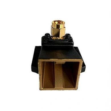
The 4.3-10 straight female to 4.3-10 straight female adapter is engineered for durability and precision. It features a straight body design that simplifies cable routing and reduces stress on connectors. The adapter’s compact form factor allows for easy integration into tight spaces, while its silver-plated contacts ensure optimal conductivity and corrosion resistance. This model is particularly suited for high-power and low passive intermodulation (PIM) systems, making it a valuable component in modern cellular and wireless infrastructure.
nn
Material and Plating Specifications
n
The adapter’s performance starts with its material selection and plating processes. Each part is carefully chosen and finished to maximize signal integrity and longevity.
nn
| Component | Material | Plating/Finish |
|---|---|---|
| Center Contact | Tin-bronze | Silver Plated |
| Outer Contact | Tin-bronze | Silver Plated |
| Body | Brass | Silver Plated |
| Dielectric | PTFE | N/A |
| Gasket | Silicon Rubber | N/A |
| Nut | Brass | Nickel Plated |
n
This combination of materials provides excellent electrical conductivity, thermal stability, and mechanical strength. The silver plating on critical contacts minimizes signal attenuation, while the PTFE dielectric ensures consistent impedance and low loss over temperature variations. The nickel-plated brass nut offers corrosion resistance and reliable mating cycle performance.
nn
Electrical Characteristics
n
The electrical specifications of the MOP-AD-MF/MF are tailored for high-frequency and high-reliability applications. The adapter delivers outstanding performance metrics that meet or exceed industry standards for 4.3-10 connectors.
nn
| Parameter | Value |
|---|---|
| Impedance | 50 Ohm |
| Frequency Range | DC – 6 GHz |
| Insulation Resistance | ≥ 10,000 MΩ |
| Dielectric Strength | 2500 V rms |
| Working Voltage | 1400 V rms |
| Insertion Loss | ≤ 0.10 dB @ DC – 3 GHz |
| VSWR | ≤ 1.10 @ DC – 3.0 GHz |
| PIM (2×43 dBm) | ≤ -160 dBc |
n
The low VSWR and insertion loss figures ensure minimal signal reflection and power loss, preserving system efficiency. The high passive intermodulation performance (≤ -160 dBc) makes this adapter ideal for dense multi-carrier environments where signal purity is paramount. The broad frequency range from DC to 6 GHz allows it to support both legacy and next-generation wireless protocols.
n
Contact Resistance Performance
n
Contact resistance is a critical factor for maintaining signal quality and preventing overheating. The adapter’s design ensures consistently low resistance values across all interfaces.
nn
| Interface Type | Center Contact | Outer Contact |
|---|---|---|
| 4.3-10 Type | ≤ 0.4 MΩ | ≤ 1.0 MΩ |
| Mini Din Type | ≤ 0.4 MΩ | ≤ 0.2 MΩ |
n
As shown, the outer contact resistance for Mini Din interfaces is particularly low, enabling excellent ground continuity and reduced interference. These values contribute to the adapter’s overall reliability in demanding network environments.
nn
Environmental and Mechanical Specifications
n
The MOP-AD-MF/MF is built to withstand harsh operating conditions without compromising performance. Its mechanical durability ensures long service life in field deployments and test setups.
nn
| Parameter | Value/Specification |
|---|---|
| Durability (matings) | ≥ 500 cycles |
| Thermal Shock Test | MIL-STD-202F, Method 107G, Condition B |
| Vibration Test | MIL-STD-202, Method 204, Condition B |
| Temperature Range | -65°C to +165°C |
| RoHS Compliance | Yes |
n
The adapter’s ability to endure 500 mating cycles without degradation makes it suitable for frequent connect and disconnect applications. Its wide temperature range and compliance with MIL-STD-202 shock and vibration tests ensure reliable operation in challenging outdoor and industrial environments. Being RoHS compliant, it meets environmental regulations for hazardous materials, making it safe for global use.
nn
Conclusion: A Robust Solution for Reliable Connectivity
n
The 4.3-10 straight female to 4.3-10 straight female adapter from the MOP-AD-MF/MF series delivers exceptional electrical performance, superior material quality, and rugged environmental resilience. With its low insertion loss, high PIM rating, and wide frequency support, it is an excellent choice for modern RF systems that demand signal integrity and long-term reliability. Whether deployed in cellular base stations, broadcasting networks, or laboratory test benches, this adapter provides the consistent, high-quality connectivity that engineers and technicians rely on. By investing in this adapter, you can enhance your system’s efficiency and reduce maintenance costs over its operational life.