Understanding the TNC Connector: A Critical Component for Reliable RF Performance
In the world of radio frequency (RF) engineering, the quality of your connectors can make or break a system’s performance. The TNC connector, short for Threaded Neill-Concelman, is a cornerstone of modern RF infrastructure, prized for its rugged design and consistent electrical behavior. This article explores the construction, performance metrics, and operational characteristics of a high-quality TNC connector designed for demanding applications. Whether you are deploying cellular networks, test equipment, or aerospace communication systems, the details that follow will help you evaluate whether this component meets your requirements.
From the choice of materials to the tight tolerances on electrical parameters, every aspect of a TNC connector is engineered to maintain signal integrity while withstanding environmental stress. The focus keyword RF connector specifications underpins the technical evaluation of this device, as the data presented here provides a comprehensive look at what makes a connector suitable for DC to 3 GHz applications. Let’s break down the key attributes that define this robust interconnect solution.
Construction Materials and Plating
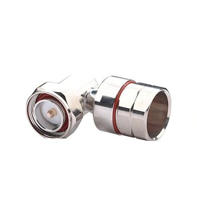
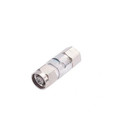
The physical durability and electrical performance of any RF connector begin with its materials. This TNC connector uses brass for both the center contact and the body/outer conductor, with a silver plating on the center contact and a tri-alloy plating on the outer conductor. Brass offers excellent machinability and conductivity, while the silver coating minimizes surface resistance at high frequencies. The tri-alloy on the outer conductor adds corrosion resistance and ensures consistent grounding. Inside, the insulator is made from PTFE (polytetrafluoroethylene), a material known for its low dielectric loss and high temperature tolerance. A silicon rubber gasket provides an environmental seal, enabling the IP67 waterproof rating.
Critical RF Connector Specifications: Electrical Performance
When engineers evaluate a connector, they focus on specific RF connector specifications that determine signal quality and system reliability. The table below consolidates all electrical and mechanical parameters for this TNC connector. These numbers are not arbitrary—they represent measurable limits that ensure stable operation across the intended frequency range.
Key Electrical Parameters
The impedance is a standard 50 ohms, matching most RF transmission lines. The frequency range extends from DC to 3 GHz, covering cellular bands, Wi-Fi, GPS, and many industrial applications. Insulation resistance exceeds 5000 megohms, and dielectric strength is rated at over 2500 volts RMS, ensuring safe operation under high-voltage transients. Contact resistances are kept below 1.0 milliohm for both center and outer contacts, which minimizes power loss. Insertion loss is exceptionally low at 0.1 dB at 3 GHz, and the voltage standing wave ratio (VSWR) is ≤1.1 at 3 GHz, indicating excellent impedance matching.
| Parameter | Specification |
|---|---|
| Impedance | 50 Ohm |
| Frequency Range | DC ~ 3 GHz |
| Insulation Resistance | ≥5000 MΩ |
| Dielectric Strength | ≥2500 V rms |
| Center Contact Resistance | ≤1.0 mΩ |
| Outer Contact Resistance | ≤1.0 mΩ |
| Insertion Loss | ≤0.1 dB @ 3 GHz |
| VSWR | ≤1.1 @ 3 GHz |
Environmental and Mechanical Durability
Beyond pure electrical metrics, the connector’s ability to endure harsh conditions is captured by its temperature range and waterproofing. The operating temperature spans from -40°C to 85°C, covering both arctic and desert environments. The IP67 rating means it is completely protected against dust ingress and can withstand immersion in up to one meter of water for 30 minutes. The passive intermodulation (PIM) performance is also critical, especially in multi-carrier systems. This connector achieves ≤-155 dBc (2×20W), which is excellent for minimizing intermodulation distortion in transmitting systems.
| Parameter | Specification |
|---|---|
| Temperature Range | -40 ~ 85°C |
| Waterproof Rating | IP67 |
| PIM (2×20W) | ≤-155 dBc |
Why These RF Connector Specifications Matter
Understanding the RF connector specifications is essential for selecting the right component. Low insertion loss and VSWR values ensure that signal power is transmitted efficiently, reducing the need for amplifiers or repeaters. High insulation resistance and dielectric strength protect equipment from voltage spikes and environmental moisture. The combination of silver-plated brass and PTFE provides a low-loss path that remains stable over temperature fluctuations. For system integrators, the IP67 rating allows deployment in outdoor or industrial settings without additional enclosures.
Furthermore, the PIM specification is increasingly important as networks densify. Poor PIM performance can create interference that degrades data throughput, especially in LTE and 5G systems. A value of -155 dBc ensures that the connector contributes negligible distortion. In applications such as remote radio heads, base stations, or antenna feed networks, these detailed RF connector specifications translate directly into field reliability and lower total cost of ownership.
Material and Plating Details
The construction choices directly affect the electrical and mechanical life of the connector. Brass provides a strong, corrosion-resistant base, while silver plating on the center contact offers superior conductivity at RF frequencies. The tri-alloy plating on the outer conductor combines nickel, copper, and other elements to prevent oxidation and maintain a low-resistance ground path. PTFE insulation supports high-frequency signals with minimal dielectric loss. The silicon rubber gasket ensures a repeatable seal, critical for maintaining IP67 performance over many mating cycles.
| Component | Material | Plating/Coating |
|---|---|---|
| Center Contact | Brass | Silver |
| Insulator | PTFE | N/A |
| Body & Outer Conductor | Brass | Tri-alloy |
| Gasket | Silicon Rubber | N/A |
Conclusion: Selecting a Connector Based on Solid Specifications
A TNC connector built to the RF connector specifications outlined here delivers reliable performance from DC to 3 GHz, with low loss, excellent impedance matching, and robust environmental protection. When designing or maintaining RF systems, the choice of interconnect should not be an afterthought. The data presented—impedance, resistance, loss, PIM, and environmental ratings—provides a clear benchmark for quality. By adhering to these parameters, engineers can ensure that their signal paths remain clean and dependable, even in challenging conditions. Whether you are upgrading an existing network or building a new one, these specifications serve as a reliable guide for connector selection.