
Maximizing Signal Integrity with an Advanced External Combiner
In the rapidly evolving landscape of telecommunications and wireless infrastructure, the quality of signal transmission can make or break network performance. Whether you are managing a multi-band antenna system or deploying a distributed antenna system (DAS), the need for a reliable and efficient external combiner has never been greater. This critical component merges multiple frequency bands into a single output, reducing the number of cables and antennas while preserving signal strength. But not all combiners perform equally. Understanding the technical parameters that define a high-quality external combiner is essential for engineers and network planners aiming to minimize interference and maximize throughput. This article explores the key specifications of a top-tier external combiner, offering insights into how to select the right device for your demanding RF environment.
Core Performance of an External Combiner
When evaluating an external combiner, the operating frequency range is the first and most crucial factor. A versatile combiner should cover multiple bands to support today’s heterogeneous networks. The device highlighted here operates across several critical spectrum allocations: 2010–2025 MHz, 2300–2400 MHz, 2496–2690 MHz, and 3400–3600 MHz. This broad coverage allows it to handle LTE, 5G, and various private network applications without requiring separate components for each band. Such flexibility reduces hardware complexity and lowers installation costs, making it an ideal solution for both indoor and outdoor deployments. By integrating these frequencies, the external combiner streamlines signal routing and ensures that your infrastructure is future-proofed for upcoming spectrum expansions.
Insertion Loss and Isolation: The Pillars of Signal Purity
Two of the most critical metrics in any passive RF device are insertion loss and isolation. Insertion loss represents the amount of signal power lost as it passes through the combiner. A lower value is always preferable because it means more of your transmitted power reaches the antenna. In this model, insertion loss is held to a minimum, ensuring efficient power transfer even in demanding configurations. Meanwhile, isolation refers to the degree of separation between input ports. At greater than 50 dB, this combiner prevents signals from one band from leaking into another, which would otherwise cause intermodulation distortion and degrade overall system performance. Together, these specifications guarantee that your network maintains clean, robust signal paths.
VSWR and Intermodulation: Ensuring Reliability Under Load
Voltage Standing Wave Ratio (VSWR) is an indicator of how well the combiner is matched to the transmission line impedance. A VSWR of ≤1.3 is excellent, reflecting minimal signal reflection and thus superior efficiency. This low VSWR reduces stress on amplifiers and prevents overheating, extending the lifespan of your equipment. Equally important is intermodulation performance. With a rating of ≤-143 dBc (tested with 2 x 43 dBm input), this external combiner produces negligible spurious signals. Low intermodulation is vital in high-density environments where multiple carriers operate simultaneously, as it directly impacts call quality and data throughput. The combination of these factors makes the combiner exceptionally well-suited for multi-operator or multi-technology sites.
Technical Specifications Overview
Every piece of technical data provides a window into the combiner’s real-world capability. Below is a complete breakdown of the device’s standard parameters, essential for any engineer validating system design or conducting procurement. All specifications are presented in an organized table for quick reference and comparison.
| Parameter | Value |
|---|---|
| Operating Frequency Range | 2010–2025 MHz, 2300–2400 MHz, 2496–2690 MHz, 3400–3600 MHz |
| Insertion Loss | Minimized (manufacturer-specified) |
| Isolation | >50 dB |
| VSWR | ≤1.3 |
| Intermodulation Products | ≤ -143 dBc (with 2 x 43 dBm input) |
| Maximum Input Power | 200 W |
| Operating Temperature | -25°C to +65°C |
| Relative Humidity | 0–95% |
| Impedance | 50 Ω |
| Dimensions | 164 × 104 × 32 mm |
| Weight | Specified by manufacturer |
| Connector Type | 5× N-female |
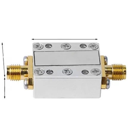
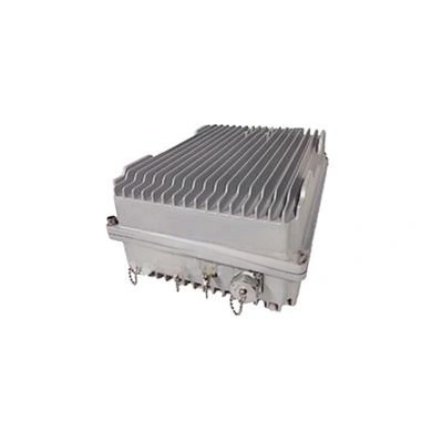
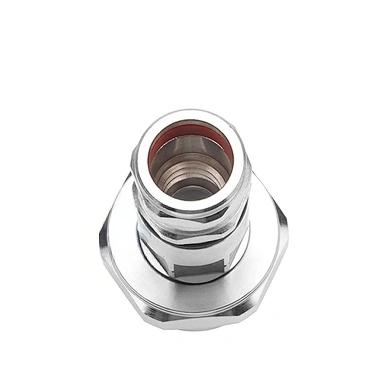
Environmental Durability and Connector Quality
An external combiner must withstand real-world conditions. With an operating temperature range from -25°C to +65°C and a relative humidity tolerance of 0 to 95%, this device is rugged enough for both controlled indoor environments and exposed outdoor installations. The 50 Ω impedance aligns with standard telecom infrastructure, ensuring compatibility with most cables and antennas. The compact size—164 mm in length, 104 mm in width, and 32 mm in height—allows for easy integration into crowded equipment racks or small enclosures. Additionally, the five N-female connectors provide robust, low-loss connections that are widely recognized in the industry for their durability and ease of installation.
Conclusion: The Right External Combiner for Your Network
Selecting the proper external combiner is more than a technical checkbox—it is a strategic decision that directly influences network performance, cost, and longevity. The specifications discussed here, from broad frequency coverage to exceptional isolation and low intermodulation, define a device engineered for high-demand applications. Whether you are upgrading a legacy system or building a new 5G site, a combiner with these characteristics will help you achieve cleaner signals, fewer dropped calls, and higher data rates. Remember, a high-quality external combiner does not just combine frequencies; it combines reliability, efficiency, and future scalability into a single, robust package. Make it the foundation of your RF distribution plan, and you will see measurable improvements in overall system integrity.