Unleashing the Power of Your Signal Generator with This 100W RF Amplifier
nn
In the world of radio frequency (RF) testing and communication, the quality of your signal source is only half the battle. To truly push the limits of your equipment, you need a robust and reliable power amplifier. This high-performance component is meticulously engineered to work seamlessly with your signal generator or signal source, transforming its output into a powerful, clean, and controllable signal. Operating across the critical 600MHz to 1000MHz frequency band, this amplifier delivers a staggering peak output of 100W, making it an indispensable tool for engineers, researchers, and system integrators. Whether you are conducting electromagnetic compatibility (EMC) testing, driving an antenna for communication, or developing high-power RF systems, this amplifier ensures your signal source reaches its full potential.
nn
This article explores the technical specifications, advanced monitoring capabilities, and practical applications of this versatile unit. By the end, you will understand why this amplifier is the perfect partner for your signal generator and signal source systems, providing not just raw power but also precision, stability, and intelligent protection.
nn
Core Technical Specifications for Your Signal Generator Amplifier
nn
Understanding the raw performance metrics is crucial. The following table details the key electrical and operational parameters of this 100W amplifier, designed to boost your signal source with exceptional fidelity.
nn
| Parameter | Specification | Remark / Condition |
|---|---|---|
| Working Frequency | 600M – 1000MHz | Full band coverage |
| Output Power (P1dB) | 100W | Peak power, adjustable down to 10W |
| Operating Voltage | 28V DC (24 – 36V range) | Standard 28V supply |
| Conversion Efficiency | ≥42% | @ 100W output |
| Adjustable Output Power | 10W ~ 100W | Software set via ALC |
| ALC Power Adjustment Range | ≥20dB | Voltage controlled attenuation |
| Gain | 50 ± 1.0dB | Stable over temperature and frequency |
| In-band Fluctuation | ≤ 2.5dB | Peak spurious emissions |
| Spurious (In-band) | ≤ -15dBm/1MHz | Measured at max output with CW signal |
| Spurious (Out-of-band 9K-1G) | No higher than noise floor | |
| Spurious (Out-of-band 1G-12.75G) | No higher than noise floor | |
| Max Input Power (no damage) | ≥ +10dBm | Lasts 1 minute |
| Input VSWR | ≤ 1.35 | With +28V, standard output -10dBm |
| Output VSWR | ≤ 1.35 | No power, standard output -10dBm |
| Output VSWR (Powered) | ≤ 1.35 | Tested with dual directional coupler |
| Working Temperature | -10°C ~ +65°C | Low temperature start-up and monitoring |
| Gain Stability | ±1.5dB | @ -40°C ~ +65°C |
| Power Stability | ±1dB | @ -40°C ~ +65°C |
| Power Requirements | ≥8.5A @ +28Vdc | CW output 100W |
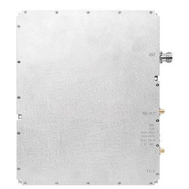
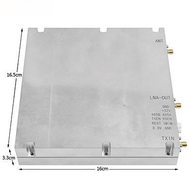
| Communication Interface | RS485 | 7W2 Male connector (Pin 1: 485A, Pin 2: 485B) |
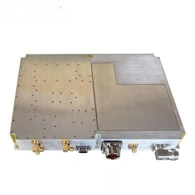
| RF Output Connector | N-Female | With 3 LED indicators (Power, Run, Alarm) |
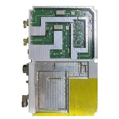
| Physical Form | Integrated module | Designed for mounting on a heat sink |
| Dimensions / Weight | Contact manufacturer | For specific dimensions and weight |
nn
Advanced Monitoring and Protection for Reliable Signal Boosting
nn
When driving critical applications, an amplifier must do more than just amplify. This unit acts as an intelligent guardian for your signal chain. Its comprehensive monitoring system is designed to protect both the amplifier and the valuable signal source you are using. The RS485 communication protocol allows for seamless integration into automated test systems, enabling remote control and status queries directly from your control software.
nn
Setting and Control Parameters
nn
Operators can configure the amplifier’s behavior through the digital interface. This includes fundamental controls like switching the amplifier on or off and enabling the alarm system. The core power management feature is the Downlink Power Control, which allows you to set the maximum output power. With a ≥20dB adjustment range, you can easily set high, medium, and low power levels to perfectly match the needs of your signal generator and the device under test (DUT).
nn
Comprehensive Alarm and Protection Systems
nn
The amplifier incorporates a sophisticated alarm system to ensure long-term reliability. These alarms automatically trigger protective actions and can be queried remotely:
nn
- n
- Over-Temperature Alarm: The amplifier will automatically shut down if its internal temperature exceeds a configurable threshold (default 85°C). It will auto-recover when the temperature drops to 65°C.
- Over-Power Alarm: Triggers when the actual output power is 2dB higher than the ALC start control threshold, protecting your downstream equipment.
- VSWR Alarm: If the output voltage standing wave ratio (VSWR) exceeds 4.0, the amplifier automatically powers off, safeguarding against antenna or load mismatch.
- Over-Current Alarm: The amplifier will shut down if the operating current exceeds 12A, protecting the power supply and internal circuitry.
- Under-Power Alarm: Alerts the user if the output power drops below 33dBm, indicating a potential issue with the signal source or the amplifier itself.
- Over-Voltage and Under-Voltage Alarms: The system monitors the supply voltage. It will shut down if voltage exceeds 32V to prevent damage.
n
n
n
n
n
n
nn
Remote Status Query Functions for Your Signal Source System
nn
Beyond setting parameters, the amplifier can provide real-time feedback for system-level diagnostics. This ability to query the amplifier’s status is crucial for automated test sequences where your signal generator must be paired with a trustworthy, self-monitoring amplifier. Queried parameters include:
nn
- n
- Amplifier Switch Status: Confirms whether the amplifier is in an ON or OFF state.
- Downstream Output Power Level: Detects and reports the output power with a detection accuracy of Pout ±1dB within a range of (Pomax+2, Pomax-20).
- Downward Standing Wave Ratio (VSWR): Typically reads 1.2 under normal load and 4.0 when mismatched.
- Temperature Query: Reports the internal module temperature with a detection error of ±3°C.
- ALC Value Query: Displays the actual, set ALC value.
- Voltage and Current Detection: Monitors the module’s working voltage and operating current for proactive diagnostics.
n
n
n
n
n
n
nn
Flexible Signal Generator Integration
nn
The amplifier is designed to work with a wide variety of signal sources. To further enhance its utility, it includes advanced frequency setting modes that can be configured via the RS485 interface, allowing the amplifier or an associated signal generator module to operate in different modes:
nn
- n
- Frequency Setting Mode 1: Set any single frequency point within the range. The frequency setting accuracy is 1MHz.
- Frequency Setting Mode 2: Set a broadband frequency sweep mode, defining start/stop frequencies, intervals, and step size.
- Frequency Setting Mode 3: Define up to 4 sub-frequency segments for targeted test sequences.
n
n
n
nn
This flexibility makes the amplifier an integral part of a complete, software-controlled signal generation and amplification system.
nn
Conclusion: The Ideal Amplifier for Your Signal Generator Needs
nn
This 100W power amplifier stands out as a professional-grade solution for anyone needing to boost the output of their signal generator or signal source. Its combination of high efficiency, flat gain, broad frequency coverage, and intelligent protection features makes it a versatile and reliable asset. Whether integrated into a complex test bench for EMC pre-compliance testing or deployed in a permanent communication installation, this amplifier delivers consistent performance. The remote monitoring and control capabilities via RS485 ensure it fits perfectly into modern, automated environments, providing both raw power and the peace of mind that comes from comprehensive system safeguards. For your next project requiring clean, high-power RF signals, this amplifier is the definitive choice to amplify your signal source’s capabilities.