Unlocking Seamless Connectivity: An In-Depth Look at Cutting-Edge Signal Booster Specifications
nnIn the rapidly evolving world of telecommunications, maintaining a strong and stable signal is no longer a luxury—it’s a necessity. Whether you are managing a sprawling commercial facility, optimizing a remote office, or ensuring uninterrupted communication in a residential setting, the performance of your signal amplification equipment is paramount. At the heart of every reliable coverage solution lies a sophisticated piece of engineering designed to capture, amplify, and rebroadcast weak cellular signals. The device under discussion here is a prime example of such technology, offering robust performance across multiple frequency bands. To truly appreciate its capabilities, we must parse through its intricate specifications, particularly concerning frequency, power, and signal integrity. This article dives deep into the technical parameters that define high-performance signal boosters, unpacking the details that engineers and installers need to know.nn
Understanding the Core Signal Booster Specifications
nnThe foundation of any signal booster’s effectiveness is its ability to handle diverse cellular frequencies. This unit supports a wide array of bands, including the 925.1-939.5 MHz, 880.1-894.5 MHz, 1849.9-1864.9 MHz, 1754.9-1769.9 MHz, 2130-2150 MHz, and 1940-1960 MHz ranges. This comprehensive coverage ensures compatibility with major 2G, 3G, and 4G LTE networks, making it a versatile tool for modern connectivity challenges. When examining these numbers, it becomes clear that the device is engineered to handle both uplink and downlink signals effectively, bridging the gap between the end-user device and the provider’s tower.nn
Power Precision: Automatic Level Control and Output Stability
nnOne of the most critical aspects of any amplifier is its power management. The signal booster specifications reveal a maximum total output power of 30±2 dBm, a figure that balances strong amplification with regulatory compliance. However, raw power is useless without control. The built-in Automatic Level Control (ALC) is where this device truly shines. When the input signal level increases by less than 10 dB, the ALC ensures the output power remains within ±2 dB of the maximum. This prevents over-amplification and potential interference. If the input signal rises by more than 10 dB, the system either holds the output within that same ±2 dB tolerance or shuts the output off entirely. This dual-layer protection is essential for maintaining signal quality and preventing damage to the equipment or connected networks.nn
Gain, Input, and Ripple: The Fine Print of Performance
nnBeyond power, the gain of a booster dictates how effectively it can revive weak signals. This unit boasts a gain of 80±3 dB and 75±3 dB across different bands, with an adjustable range of ≥42 dB. The step size for adjustments is a precise 1 dB, allowing for granular tuning. However, the gain adjustable error shows a variance: ≤|±1.0| dB for adjustments of 0-10 dB and 10-20 dB, and ≤|±1.5| dB for adjustments ≥21 dB. This level of precision is vital for fine-tuning coverage without introducing distortion. The ripple in the band is ≤5 dB, and the voltage standing wave ratio (VSWR) is ≤1.8—both indicators of excellent impedance matching and low signal reflection.nn
Critical Metrics: Noise, Delay, and Error Vector Magnitude
nnA signal is only as good as its clarity. The noise figure of ≤5 dB ensures that the amplifier introduces minimal background noise, preserving the original signal’s integrity. A time delay of ≤1 μs is nearly imperceptible, ensuring real-time communication without lag. Furthermore, the Error Vector Magnitude (EVM) is ≤8%, a crucial signal booster specification for digital transmissions. Low EVM means that the modulated signal remains accurate, reducing the risk of data errors during high-speed transfers. These parameters collectively define the difference between a usable booster and an exceptional one.nn
Spurious Emissions and Adjacent Channel Leakage Ratio
nnCompliance with spectral purity standards is non-negotiable. The spurious emission limits are stringent: from 9 kHz to 150 kHz (with a 1 kHz bandwidth), the emission must be ≤-36 dBm. This tight control extends across the spectrum up to 12.75 GHz, where it is ≤-30 dBm. Adjacent Channel Leakage Ratio (ACLR) is equally impressive, with values of ≤ -40 dBc at ±10 MHz and ≤ -45 dBc at ±20 MHz. These figures ensure that the booster does not interfere with neighboring channels, a common issue in congested urban environments.nn
Physical and Environmental Signal Booster Specifications
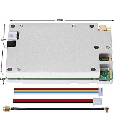
nnDurability and ease of installation are factored into the design. The unit operates on a power supply of AC90-264V@50/60Hz, making it globally compatible. The RF connector is an N-Female type, a standard choice for professional installations requiring reliability. The impedance is 50 ohms, the industry norm for RF equipment. Environmentally, the booster is rated for operation from -25℃ to +55℃ with humidity ≤95%, and it is protected to IP35. Dimensions are ≤420 x 268 x 58 mm, with a weight of ≤6 kg, making it relatively compact for its capabilities.nnTo consolidate these details, the comprehensive technical data is organized in the table below:nn
| Parameter | Value / Range |
|---|---|
| Frequency Range (MHz) | 925.1-939.5, 880.1-894.5, 1849.9-1864.9, 1754.9-1769.9, 2130-2150, 1940-1960 |
| Max. Total Output Power (dBm) | 30±2 |
| Automatic Level Control (ALC) | Input increase <10dB: output ±2dB; Input increase ≥10dB: output ±2dB or off |
| Maximum Allowable Input Level (dBm) | -10 |
| Gain (dB) | 80±3 / 75±3 |
| Gain Adjustable Range (dB) | ≥42 |
| Gain Adjustment Step Size (dB) | 1 |
| Gain Adjustable Error (dB) | 0-10: ≤|±1.0|; 10-20: ≤|±1.0|; ≥21: ≤|±1.5| |
| Frequency Error (ppm) | ≤0.05 |
| Ripple In Band (dB) | ≤5 |
| VSWR | ≤1.8 |
| Noise Figure (dB) | ≤5 |
| Time Delay (μs) | ≤1 |
| EVM | ≤8% |
| Spurious Emission (dBm) | 9kHz-150kHz/1kHz: ≤-36; 150kHz-30MHz/10kHz: ≤-36; 30MHz-80MHz/100kHz: ≤-36; 80MHz-1GHz/100kHz: ≤-36; 1GHz-12.75GHz/1MHz: ≤-30 |
| ACLR (dBc) | ±10MHz: ≤-40; ±20MHz: ≤-45 |
| Power Supply | AC90-264V @ 50/60Hz |
| RF Connector | N-F |
| Impedance (Ω) | 50 |
| Environment Requirement | -25℃ to +55℃, humidity ≤95% |
| Waterproof | IP35 |
| Dimension (mm) | ≤420 x 268 x 58 |
| Weight (kg) | ≤6 |
nn
Conclusion: Mastering the Details for Superior Coverage
nnIn conclusion, the journey through these signal booster specifications reveals a device engineered for precision, reliability, and high-performance amplification. From the meticulous frequency coverage spanning multiple cellular bands to the sophisticated ALC that prevents signal overload, every parameter contributes to a solution that can handle demanding environments. The low noise figure, minimal time delay, and stringent spurious emission limits ensure that the boosted signal remains clean and compliant. Whether you are installing a network in a challenging building or deploying coverage for critical communications, understanding these specifications is the first step toward success. By focusing on the technical details—such as gain stability, EVM, and environmental tolerance—you can select a booster that not only meets but exceeds your connectivity needs, ensuring every call and data session is crystal clear.