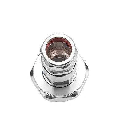
4.3-10 Female Connector for 1/2″ Feeder Cable: Performance and Design
nn
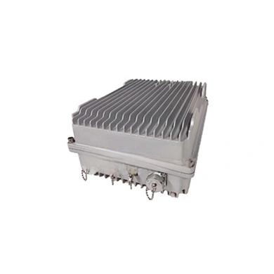
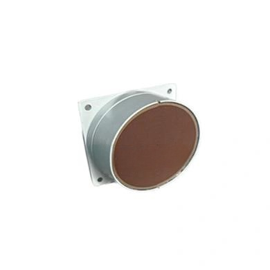
The 4.3-10 female connector designed for 1/2″ feeder cable stands as a pivotal component in modern telecommunications infrastructure. This connector type has gained widespread adoption across base stations, distributed antenna systems (DAS), and small cell deployments due to its compact footprint, superior passive intermodulation (PIM) performance, and robust mechanical design. Engineers and network operators increasingly rely on this interface to ensure reliable signal transmission in both 4G LTE and emerging 5G networks, where signal integrity and minimal loss are non-negotiable.
nn
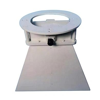
Understanding the technical nuances of this connector is essential for anyone involved in RF system design or field installation. The 4.3-10 interface offers a distinct advantage over legacy interfaces such as the 7-16 DIN connector by providing comparable electrical performance in a significantly smaller form factor. This reduction in size correlates directly with improved port density on remote radio units (RRUs) and antennas, enabling more compact and efficient network hardware designs. Moreover, the blind-mating capability and color-coded coding options simplify installation and reduce the risk of connector damage during deployment.
nn
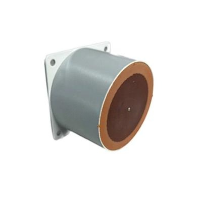
When selecting a 4.3-10 female connector for 1/2″ feeder cable, several critical factors demand attention. The material composition of each component directly influences both immediate electrical performance and long-term reliability in outdoor environments. Silver-plated contacts, for instance, ensure low contact resistance and excellent corrosion resistance, while the PTFE dielectric provides stable impedance characteristics across a wide frequency range. The following table details the exact material specifications and plating choices used in premium-grade connectors.
nn
Material and Plating Specifications
nn
| Component | Base Material | Plating/Coating |
|---|---|---|
| Center Contact | Tin-bronze | Silver |
| Outer Contact | Tin-bronze | Silver |
| Body | Brass | Silver |
| Dielectric | PTFE (Polytetrafluoroethylene) | — |
| Gasket | Silicone Rubber | — |
| Nut | Brass | Nickel |
nn
The choice of silver plating for key conductive components is deliberate, as silver offers the highest electrical conductivity among common plating materials. This translates directly into lower insertion loss and improved PIM performance. The nickel-plated brass nut provides the necessary mechanical strength for repeated tightening cycles while resisting galling—a common failure mode when stainless steel components are used without proper lubrication.
nn
Electrical Characteristics of the 4.3-10 Female Connector
nn
The electrical performance parameters define the operational boundaries and suitability of this connector for various applications. These characteristics must be verified through rigorous testing to ensure compliance with industry standards such as IEC 60169-54 and relevant ETSI specifications. For the 4.3-10 female connector designed for 1/2″ feeder cable, the key electrical specifications are summarized in the comprehensive table below.
nn
Electrical and Mechanical Performance Data
nn
| Parameter | Specification | Condition/Notes |
|---|---|---|
| Impedance | 50 Ω | Nominal |
| Frequency Range | DC – 2.5 GHz | Applicable for typical cellular bands |
| Insulation Resistance | ≥ 10,000 MΩ | At 500 V DC |
| Contact Resistance (Center) | ≤ 5 mΩ | N type interface |
| Contact Resistance (Outer) | ≤ 1.0 mΩ | Between outer conductors |
| Dielectric Strength | 2,500 V rms | At sea level, 50 Hz |
| Working Voltage | 1,400 V rms | Maximum continuous |
| Insertion Loss | ≤ 0.10 dB | DC – 3 GHz |
| VSWR | ≤ 1.20 | DC – 3.0 GHz |
| PIM (2 × 43 dBm) | ≤ -160 dBc | Static test, 2 carriers |
| Durability | ≥ 500 mating cycles | Without performance degradation |
| Temperature Range | -40 °C to +85 °C | Operational and storage |
| RoHS Compliance | Yes | Directive 2011/65/EU |
nn
Several aspects of these specifications merit closer examination. The ≤0.10 dB insertion loss performance ensures that even in long cable runs or cascaded connector chains, total system loss remains manageable. The VSWR specification of ≤1.20 across the entire frequency band indicates excellent impedance matching, which minimizes signal reflections and potential interference. Most critically, the PIM specification of ≤-160 dBc is a stringent requirement that ensures this connector does not generate harmful intermodulation products in sensitive receiver bands—a common challenge in high-power, multi-carrier environments.
nn
Environmental and Mechanical Resilience
nn
The 4.3-10 female connector for 1/2″ feeder cable is engineered to withstand harsh outdoor conditions. The silicone rubber gasket provides an effective environmental seal when mated, preventing moisture ingress that could degrade electrical performance over time. The 500-cycle durability rating ensures reliable operation through multiple installation and maintenance events, while the wide temperature range accommodates deployments from arctic climates to desert heat. The RoHS compliance confirms adherence to environmental regulations concerning hazardous substances, making this connector suitable for global markets with stringent environmental standards.
nn
In conclusion, the 4.3-10 female connector for 1/2″ feeder cable represents a well-engineered solution that balances compact size with exceptional electrical performance. By carefully selecting materials, optimizing the interface design, and adhering to rigorous test specifications, manufacturers deliver connectors that meet the demanding requirements of modern wireless networks. Whether upgrading existing infrastructure or deploying new 5G sites, specifying this connector type ensures reliable signal integrity, low maintenance costs, and long-term operational stability. Network designers and installers alike benefit from understanding these specifications, as they directly impact system performance and total cost of ownership over the network lifecycle.