Understanding Low PIM Attenuators: Key Specifications and Applications
nnIn the world of RF and microwave communications, signal integrity is everything. Engineers and network installers constantly battle interference, reflections, and distortion to ensure clean, reliable data transmission. One critical component that often goes overlooked is the low PIM attenuator. This device reduces signal power while introducing minimal passive intermodulation (PIM)—a type of distortion that can degrade network performance. Whether you’re testing cellular base stations, optimizing satellite links, or fine-tuning a 5G network, choosing the right attenuator starts with understanding its electrical characteristics.nn
Why Power Handling and Frequency Range Matter
nnEvery low PIM attenuator is designed to operate within specific power and frequency boundaries. The power rating, expressed in watts (W), indicates how much RF energy the component can safely dissipate without overheating or failing. Common options range from 5W to 200W. Similarly, the frequency range defines the band over which the attenuator maintains its specified performance. For most modern applications, DC-3GHz or DC-6GHz covers everything from legacy 2G/3G systems to advanced 5G sub-6 GHz deployments. Exceeding these limits can lead to increased VSWR, higher insertion loss, and even permanent damage.nn
Electrical Specifications of Low PIM Attenuators: A Detailed Breakdown
nnTo select the correct low PIM attenuator, you must examine its electrical parameters carefully. Below are the standard specifications for typical models. Note that values may vary based on power rating and manufacturer.nn
| Parameter | Value(s) / Range |
|---|---|
| Power (W) | 5, 10, 25, 50, 100, 200 |
| Frequency Range | DC–3 GHz / DC–6 GHz |
| Attenuation Value (dB) | 3, 6, 10, 15, 20, 30 |
| In-Band Ripple (dB) | ≤0.3 / ≤0.5 / ≤0.7 / ≤0.8 / ≤1.0 / ≤1.2 |
| Impedance (Ω) | 50 |
| VSWR | ≤1.2:1 |
| PIM3 (dBc) | ≤ –120 @ 2×33 dBm; ≤ –105 @ 2×43 dBm |
| PIM5 (dBc) | ≤ –145 @ 2×33 dBm; ≤ –120 @ 2×43 dBm |
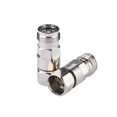
| Connector Type | N-Male, N-Female |
| Operating Temperature (°C) | –20 to +55 |
| Humidity | ≤95% |
nn
Advanced Low PIM Attenuator Specifications for High-Performance Networks
nnFor applications demanding the lowest possible distortion, custom-engineered low PIM attenuator models deliver even tighter performance. These units are ideal for lab testing, high-reliability installations, and mission-critical infrastructure. Key differences include extended temperature range and superior PIM suppression.nn
| Parameter | Value(s) / Range |
|---|---|
| Power (W) | 5, 25, 50, 100, 200 |
| Frequency Range | DC–3 GHz / DC–6 GHz |
| Attenuation Value (dB) | 3, 6, 10, 15, 20, 30 |
| In-Band Ripple (dB) | ≤0.3 / ≤0.5 / ≤0.7 / ≤0.8 / ≤1.0 / ≤1.2 |
| Impedance (Ω) | 50 |
| VSWR | ≤1.2:1 |
| PIM3 (dBc) | ≤ –155 @ 2×43 dBm |
| Connector Type | N-Male, N-Female |
| Operating Temperature (°C) | –30 to +65 |
| Humidity | ≤95% |
nn
How to Choose the Right Low PIM Attenuator for Your System
nnSelecting a low PIM attenuator involves matching its specifications to your system’s requirements. Start by identifying the maximum power your signal chain will encounter. For example, a 50W attenuator is sufficient for most indoor base station tests, while outdoor tower-mounted units may need 200W to handle combined carrier power. Next, verify that the frequency range covers all operating bands—DC-6GHz components are future-proof for emerging 5G mid-band deployments.nnAttenuation value is equally critical. A 3dB or 6dB pad is ideal for fine-tuning signal levels without excessive loss, while 20dB or 30dB pads help protect sensitive receivers. Always check the in-band ripple specification; lower ripple (e.g., ≤0.3 dB) ensures flatter frequency response, which is vital for wideband systems. The VSWR of ≤1.2:1 guarantees minimal reflections, preserving impedance matching and reducing system noise.nn
PIM Performance: The Defining Characteristic of a True Low PIM Attenuator
nnThe term “low PIM” directly refers to the attenuator’s ability to suppress intermodulation distortion. PIM occurs when two or more high-power signals mix in nonlinear components, creating spurious signals that interfere with reception. For a low PIM attenuator, the third-order PIM (PIM3) is typically specified at ≤ –120 dBc with two +33 dBm carriers. Advanced models achieve ≤ –155 dBc at +43 dBm, meeting the strictest requirements for cellular and Wi-Fi networks. Always compare PIM values at your actual operating power levels—higher carrier powers demand better PIM performance.nn
Practical Tips for Installation and Maintenance
nnProper handling maximizes the life of your low PIM attenuator. Always use torque wrenches on N-type connectors to avoid damaging the interface. Keep the unit clean and dry; humidity below 95% is essential to prevent corrosion and PIM degradation. Operate within the temperature range: standard models work from –20°C to +55°C, while extended-range versions tolerate –30°C to +65°C for outdoor cabinets or unheated shelters.nn
Conclusion
nnThe low PIM attenuator is a cornerstone component in any high-performance RF system. By understanding its power handling, frequency coverage, attenuation options, and—most importantly—its PIM ratings, you can make an informed choice that ensures signal clarity and network reliability. Whether you’re deploying a 5G small cell or maintaining a legacy 4G macro site, referencing the detailed electrical specifications provided here will guide you to the perfect attenuator for your application. Remember to always verify the datasheet against your operating conditions, and you’ll enjoy years of distortion-free performance.