Understanding the MOP Series Power Splitter: Robust Performance for Modern Networks
n
When designing or maintaining a telecommunications network, the reliability and precision of every component matter. The MOP series power splitter, particularly models MOP-PS-727-200(300/500)-XXNF(MF/DF) and MOP-PS-740-200(300/500)-XXNF(MF/DF), stands out as a critical element for distributing signals efficiently. Whether you are working with 4G LTE infrastructure or preparing for 5G rollouts, these devices offer the flexibility and durability needed to handle demanding RF environments. In this article, we will explore the key specifications, design choices, and applications that make the MOP power splitter a top-tier choice for engineers and installers alike.
n
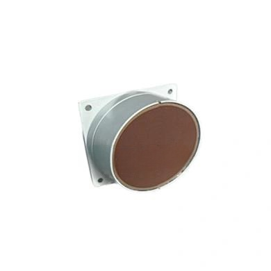
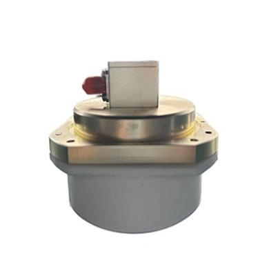
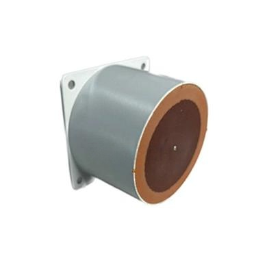
The MOP power splitter is engineered to meet the rigorous demands of both indoor and outdoor installations. Its robust construction ensures minimal signal degradation while supporting a wide range of frequencies. With options for different split ways and power handling capabilities, this component adapts to varied system requirements without compromising on performance. Understanding how to select the right model for your network can significantly impact overall system efficiency and long-term reliability.
nn
Technical Specifications of the MOP Power Splitter
n
To evaluate whether the MOP power splitter fits your project, it is essential to examine its technical parameters. The following table provides a comprehensive overview of the key specifications for both model series. Note how factors like frequency range, insertion loss, and intermodulation distortion vary between the 727 and 740 models, enabling you to choose the optimal balance for your specific application.
n
| Parameter | MOP-PS-727-200(300/500)-XXNF(MF/DF) | MOP-PS-740-200(300/500)-XXNF(MF/DF) |
|---|---|---|
| Frequency Range | 698 – 2700 MHz | 698 – 3800 MHz |
| Split Ways | 2, 3, 4 | 2, 3, 4 |
| VSWR | ≤ 1.25 : 1 | ≤ 1.25 : 1 |
| Insertion Loss (dB) | ≤ 3.3 (2-way), ≤ 5.2 (3-way), ≤ 6.4 (4-way) | ≤ 3.5 (2-way), ≤ 5.5 (3-way), ≤ 7 (4-way) |
| Average Power (W) | 200 / 300 / 500 | 200 / 300 / 500 |
| 3rd Order IMD | ≤ -155 dBc @ 2×43 dBm | ≤ -150 dBc @ 2×43 dBm |
| Impedance (Ω) | 50 | 50 |
| Connectors | Type N, 4.3-10, DIN-Female | Type N, 4.3-10, DIN-Female |
| Operating Temperature (°C) | -20 to +55 | -25 to +65 |
| Application | Indoor or Outdoor | Indoor or Outdoor |
n
Key Performance Indicators: Why Lower Insertion Loss Matters
n
When deploying a MOP power splitter, one of the most critical figures to examine is the insertion loss. As shown in the table, the loss increases with the number of split ways—this is expected because each output path introduces attenuation. However, the 727 model offers slightly lower loss figures compared to the 740 series, making it ideal for applications where signal strength must be preserved over longer cable runs. For example, a 4-way split with the 727 keeps loss under 6.4 dB, while the 740 reaches up to 7 dB. Choosing the right model here directly affects the total system budget and may reduce the need for additional amplification.
n
Intermodulation Distortion: Ensuring Clean Signals
n
The third-order intermodulation distortion (IMD) is a crucial parameter that indicates how well the MOP power splitter maintains signal purity under high-power conditions. Both models achieve excellent IMD performance, with the 727 series at ≤ -155 dBc and the 740 at ≤ -150 dBc. This means that even when handling two high-power carriers at 43 dBm each, distortion products remain extremely low, preventing interference and ensuring compliance with strict network standards. For multi-operator or multi-band setups, this level of performance is indispensable.
nn
Choosing Between the MOP-PS-727 and MOP-PS-740
n
Deciding which MOP power splitter to use depends largely on your frequency requirements and environmental conditions. The 727 model covers up to 2700 MHz, which is sufficient for most 2G, 3G, and 4G LTE bands. In contrast, the 740 supports up to 3800 MHz, making it future-proof for emerging 5G bands and higher-frequency applications. Additionally, the 740 operates across a broader temperature range (-25°C to +65°C), offering greater resilience in extreme outdoor climates. Both models share the same power handling options (200, 300, or 500 W) and connector choices, so the primary differentiators are bandwidth and thermal tolerance.
n
Connector and Configuration Flexibility
n
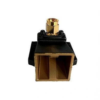
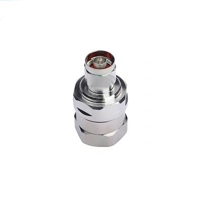
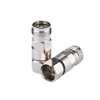
Each MOP power splitter can be ordered with Type N, 4.9-10, or DIN-Female connectors, allowing seamless integration with existing cabling. The “XXNF(MF/DF)” suffix indicates whether the unit is configured with N-female, mini-female, or DIN-female ports. This level of customization ensures that your installation remains clean and that impedance matching at 50 Ω is maintained throughout the system. Always verify connector types before ordering to avoid adapter losses.
nn
Conclusion: The MOP Power Splitter as a Foundation for Reliable RF Distribution
n
In summary, the MOP power splitter offers a compelling blend of performance, durability, and adaptability for both indoor and outdoor RF networks. With its low VSWR, controlled insertion loss, and outstanding IMD characteristics, it meets the stringent requirements of modern telecommunications. Whether you select the 727 or 740 series, you are investing in a component that ensures signal integrity across a wide frequency range. By carefully matching the splitter’s specifications—such as power handling, number of ways, and operating temperature—to your project’s needs, you can build a more efficient and reliable system. Let the MOP power splitter be the dependable backbone of your next network deployment.