Understanding the UHF/VHF Repeater and Its Critical Specifications
nn
In the world of wireless communication, ensuring reliable signal coverage across challenging terrains and large buildings is a constant battle. This is where the UHF/VHF repeater becomes an indispensable tool. These devices are engineered to capture weak signals from a base station and retransmit them, effectively bridging gaps in coverage. But not all repeaters are created equal. To select the right equipment for your network, you must dig deep into the technical parameters that define performance, efficiency, and reliability. This article demystifies the core specifications of a high-performance dual-band repeater, focusing on the 850M and 1900M frequency bands, and explains why each metric matters for maintaining a robust communication link.
nn
Whether you are a telecom engineer, a system integrator, or a facility manager, understanding these specs is the first step toward eliminating dead zones and ensuring seamless connectivity. Let’s break down the key features that make a UHF/VHF repeater a powerful asset for any coverage solution.
nn
Frequency Bands and Bandwidth: The Foundation of a UHF/VHF Repeater
nn
The first set of specifications defines the operational range of the repeater. This device is designed to work on two distinct frequency bands, each with its own uplink and downlink paths. The uplink is the signal path from the mobile device to the base station, while the downlink is the signal from the base station to the mobile device. The bandwidth allocated for each band determines how many simultaneous calls or data sessions can be supported.
nn
| Parameter | 850M Uplink | 850M Downlink | 1900M Uplink | 1900M Downlink |
|---|---|---|---|---|
| Frequency Range (MHz) | 824-849 | 869-894 | 1850-1910 | 1930-1990 |
| Bandwidth (MHz) | 25 | 25 | 60 | 60 |
nn
The 850M band offers a 25 MHz bandwidth for both uplink and downlink, which is typical for cellular applications in rural and suburban areas. In contrast, the 1900M band provides a generous 60 MHz bandwidth, supporting higher capacity in dense urban environments. The combination of these bands makes the UHF/VHF repeater versatile for different deployment scenarios.
nn
Power and Gain: Maximizing Signal Strength
nn
Two critical performance indicators are maximum output power and gain. Output power defines how strong a signal the repeater can transmit, while gain measures how much it amplifies the incoming signal. For the 850M band, the downlink output power is 33±2 dBm, while the uplink is slightly lower at 27±2 dBm. The 1900M band shares the same power levels. Gain values are equally impressive—75±3 dB for uplink and 80±3 dB for downlink. This high gain allows the repeater to work with very weak input signals and still provide a strong retransmission. The Automatic Level Control (ALC) range is 45 dB with an accuracy of ≤|±0.5| dB, ensuring the output power stays within safe limits even when input signals fluctuate.
nn
Adjustability and Precision: Fine-Tuning Your UHF/VHF Repeater
nn
Flexibility is key when deploying a repeater in real-world environments where signal conditions vary. The attenuation (ATT) adjustable range covers 0 to 31 dB in 1 dB steps, giving engineers precise control over signal reduction. The ATT adjustment error is ≤|±1.5| dB, which means the actual attenuation is very close to the set value. This level of precision helps avoid over-amplification or interference with neighboring systems. Ripple in band, measured peak-to-peak at 25°C, is ≤4.0 dB for both uplink and downlink. Low ripple ensures that the amplified signal maintains consistent power across the entire frequency band, which is crucial for clear voice and stable data transmission.
nn
Handling Adverse Conditions: Input Protection and Environmental Resilience
nn
A robust UHF/VHF repeater must tolerate high input power without damage. The maximum non-destructive input power is -10 dBm, providing a safety margin against sudden surges. Signal delay is ≤1 microsecond—an imperceptible latency that preserves real-time communication. Voltage Standing Wave Ratio (VSWR) when powered up with minimum gain and -30 dBm input is ≤1.8, indicating good impedance matching between the repeater and antennas, which reduces reflected power and potential damage. Noise figure, measured at maximum gain, is ≤8 dB, which ensures the added noise from amplification is minimal. The 3rd order intermodulation distortion is ≤-36 dBc (with dual-tone interval 600 kHz), indicating linear signal amplification with low distortion. Spurious emissions are strictly controlled: from 9 kHz to 1 GHz, emissions are ≤-36 dBm at 100 kHz resolution bandwidth; from 1 GHz to 12.75 GHz, they are ≤-30 dBm at 1 MHz resolution bandwidth. These low levels prevent the repeater from interfering with other wireless services.
nn
Physical and Operational Specifications
nn
| Parameter | Value |
|---|---|
| Radio Connector | N(f) |
| Power Consumption (Watts) | ≤60 |
| Power Supply | AC100-240V |
| Temperature Range (°C) | -25 to +55 |
| Humidity (%) | ≤95 |
| Protection Grade | IP55 |
| Alarm | LED light |
nn
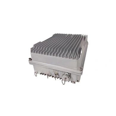
The repeater uses an N-type female connector, which is a robust standard for RF applications. Power consumption is ≤60 watts, making it energy-efficient for continuous operation. The unit operates on standard AC mains (100-240V) and can function reliably in harsh environments with temperature extremes from -25°C to +55°C and humidity up to 95%. The IP55 protection grade means it is dust-protected and can withstand water jets, making it suitable for outdoor installation. An LED alarm light provides visual status indication, simplifying maintenance and troubleshooting.
nn
Conclusion: Choosing the Right UHF/VHF Repeater
nn
From the frequency ranges and bandwidths to power, gain, and environmental resilience, every specification of a UHF/VHF repeater plays a vital role in delivering consistent signal coverage. The high gain and precise ALC ensure that weak signals are boosted without distortion, while the wide temperature and humidity tolerances guarantee operation in extreme conditions. By carefully evaluating these parameters, you can select a repeater that meets your specific needs—whether for a large commercial building, an underground parking structure, or a remote rural area. Investing in a well-specified UHF/VHF repeater is the key to eliminating dead zones and providing reliable communication for your users. Always verify that the device you choose aligns with the required frequency bands and performance metrics to achieve optimal results. With the right equipment, seamless connectivity becomes a reality.