Understanding the RF Power Tapper: The Unsung Hero of Signal Distribution
nn
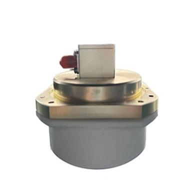
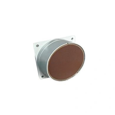
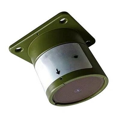
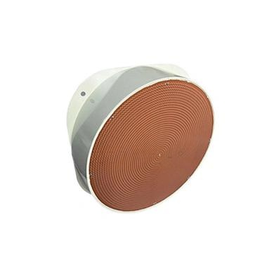
In the complex world of RF and telecommunications, signal integrity is paramount. Whether you are optimizing a cellular network, deploying a DAS (Distributed Antenna System), or testing laboratory equipment, the ability to split and monitor signal power without degrading quality is critical. This is where the RF power tapper comes into play. A power tapper, often confused with a simple splitter, is a sophisticated RF component designed to extract a small, precise portion of the signal for monitoring or testing purposes while passing the majority of the power through the main line. This device ensures that the primary communication link remains virtually unaffected, making it an indispensable tool for engineers and network technicians.
nn
The core principle of a power tapper is its directional coupling capability. Unlike a resistive splitter, which divides power and introduces significant loss, a tapper uses a carefully engineered coupler to create a predictable relationship between the input, output, and coupled ports. The result is a device that offers low insertion loss on the main path and a high degree of accuracy on the tapped port. In the following sections, we will break down the critical specifications, from frequency range to intermodulation performance, that define a high-quality tapper. By the end of this guide, you will have a comprehensive understanding of how to select the right component for your specific application.
nn
Key Specifications of a High-Performance RF Power Tapper
nn
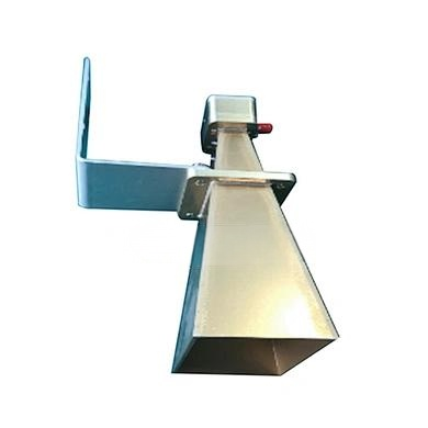
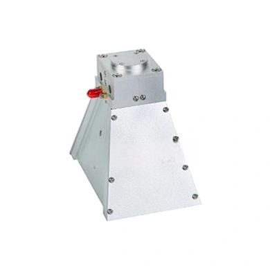
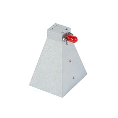
To fully appreciate the capabilities of an RF power tapper, one must examine its technical parameters. The table below presents the complete specifications for a premium directional tapper, covering a wide range of coupling values from 5 dB to 20 dB. These figures are essential for designing efficient and reliable RF distribution networks.
nn
| Parameter | 5 dB | 6 dB | 7 dB | 8 dB | 9 dB | 10 dB | 13 dB | 15 dB | 20 dB |
|---|---|---|---|---|---|---|---|---|---|
| Frequency Range | 698–4000 MHz | ||||||||
| Coupling Tolerance | ±1.5 dB | ±1.5 dB | ±1.3 dB | ±1.3 dB | ±1.3 dB | ±1.3 dB | ±1.3 dB | ±1.3 dB | ±1.3 dB |
| Insertion Loss (Main Line) | Low, dependent on coupling ratio | ||||||||
| Splitting Ratio (Through:Tap) | 1:0.33:0.67 | 1:0.25:0.75 | 1:0.2:0.8 | 1:0.16:0.84 | 1:0.11:0.89 | 1:0.1:0.9 | 1:0.05:0.95 | 1:0.03:0.97 | 1:0.01:0.99 |
| Return Loss | ≥ 17 dB | ||||||||
| VSWR | ≤ 1.35 | ||||||||
| Intermodulation Products | ≤ -150 dBc (with 2 x 43 dBm) | ||||||||
| Maximum Input Power | 300 W | ||||||||
| Operating Temperature | -25°C to +85°C | ||||||||
| Relative Humidity | 0–95% | ||||||||
| Impedance | 50 Ω | ||||||||
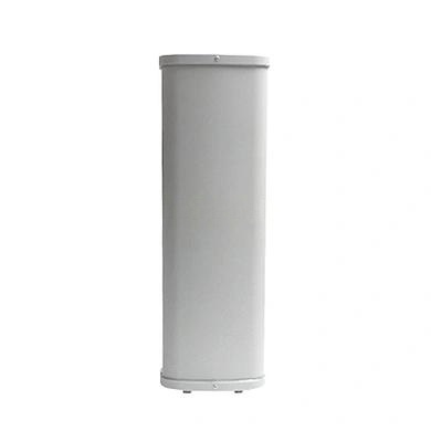
| Dimensions | 115 x 45 x 25 mm | ||||||||
| Weight | 540 g | ||||||||
| Connector Type | N Female | ||||||||
| Ingress Protection | IP65 | ||||||||
| Color | Black/Gray | ||||||||
nn
Why Coupling Value and Tolerance Matter in a Tapper
nn
The coupling value is the heart of the RF power tapper. As shown in the table, options range from 5 dB to 20 dB. A 5 dB tapper extracts a stronger signal (approximately 30% of the power) to the coupled port, making it ideal for applications requiring significant signal monitoring or where the device under test needs a robust input. Conversely, a 20 dB tapper extracts a very small fraction (around 1%) of the signal, which is perfect for high-power lines where minimal interference is desired. The coupling tolerance, refined to ±1.3 dB for most models, ensures that the exact amount of coupled power is predictable and repeatable across manufacturing batches, which is essential for calibration and sensitive measurement setups.
nn
Insertion Loss and Splitting Ratio
nn
A common misconception is that a tapper introduces heavy loss. In reality, the insertion loss on the main line is minimal, as the device is designed to pass the bulk of the signal. The splitting ratio column clarifies this: for a 10 dB tapper, 90% of the input power goes to the output port, while only 10% is diverted to the tap port. This efficiency makes the tapper a low-loss solution compared to traditional power dividers. Engineers must understand that the coupling value directly influences the splitting ratio; a higher coupling value (e.g., 20 dB) leads to a higher ratio of power on the main line (99%), preserving signal strength for downstream antennas or equipment.
nn
VSWR and Intermodulation Performance
nn
Two critical performance indicators for any RF component are VSWR (Voltage Standing Wave Ratio) and Intermodulation Distortion (IMD). The VSWR of ≤ 1.35 indicates excellent impedance matching across the entire 698–4000 MHz band, minimizing reflections and ensuring maximum power transfer. More importantly, the intermodulation products specification of ≤ -150 dBc is exceptionally low, even when tested with two high-power tones of +43 dBm each. This low PIM (Passive Intermodulation) rating is crucial for modern cellular systems, as it prevents the generation of spurious signals that could interfere with sensitive receiver bands. A high-quality RF power tapper must exhibit such low PIM to be suitable for 4G LTE and 5G NR deployments.
nn
Practical Applications and Environmental Durability
nn
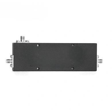
The environmental specifications further reinforce the tapper’s robustness. With an IP65 ingress protection rating, this component is dust-tight and protected against water jets from any direction, making it suitable for outdoor installations such as rooftop antennas or cell towers. The operating temperature range from -25°C to +85°C ensures reliable performance in extreme climates, from freezing winters to scorching summers. The N Female connector type is a standard in the industry, providing a secure, weatherproof connection that can handle high power levels without degradation.
nn
Choosing the Right Tapper for Your Network
nn
When selecting a power tapper, consider your specific needs. For a DAS system where you need to monitor multiple signal points without disrupting service, a 10 dB or 13 dB tapper often provides the best balance between tap signal strength and main line integrity. For laboratory testing where you need a precise sample of a high-power transmitter output, a 20 dB tapper is preferable. Always verify the frequency range compatibility—this model supports from 698 MHz up to 4000 MHz, covering all current cellular bands. The compact size of 115 x 45 x 25 mm and weight of only 540 grams also allows for easy assembly within crowded enclosure racks.
nn
Conclusion: The Essential Role of the RF Power Tapper
nn
In summary, the RF power tapper is a deceptively simple yet highly engineered component that enables efficient signal distribution, monitoring, and testing in modern telecommunications networks. By understanding the interplay between coupling value, insertion loss, VSWR, and PIM, engineers can make informed decisions that optimize network performance. The specifications detailed in this article provide a clear benchmark for quality: wide frequency coverage, tight coupling tolerances, low intermodulation products, and robust environmental protection. Whether you are upgrading a broadcast system or commissioning a new 5G site, a reliable power tapper is a foundational element that ensures your signals remain clean, powerful, and precisely controlled. Invest in a component that meets these rigorous standards, and you will have a solution that delivers consistent results for years to come.